
Introduction
This tutorial will give you a brief introduction to the concept of colors and how different colors can be produced using RGB LED. The color would be controlled using an ATMega16 microcontroller.
RGB LEDs are basically the combination of the 3 LEDs (Red, Green and Blue) fused into a single package. It consists of four pins totally out of which three of them for the three different colors. The 4th pin is common for all three colors and it’s either Cathode or Anode.

Concept of Color
Color is the visual perceptual property corresponding in humans to the categories called red, blue, yellow, green and others. (Wikipedia definition)
We know that white light (say coming from the Sun) consist of mixture of colors. Remember the prism experiment you head of when you were in school?

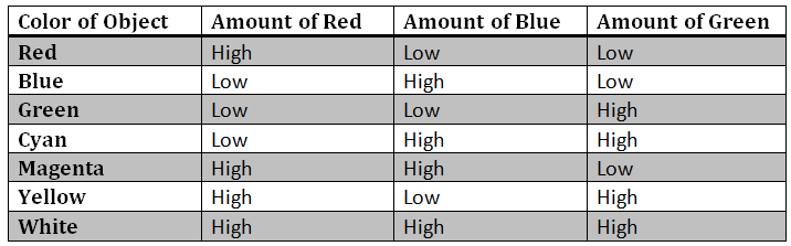
So the primary colors of light are Red, Blue and Green. All other colors we see are formed by mixing of these three colors in different proportions.

When we see an object, we are not seeing the object but actually we are seeing the light reflected by the object. Confusing isn’t it?

Let’s say that you are looking at a red car. Now the car appears red to you because it absorbs the green and blue part of the light incident on it and only allows the red part of the light to reflect.
So if you see a red colored car through a green filter (which allows only green light to pass through it), then it will appear in black color (since no light would reach your eyes)
And the conclusion is that
Concept of PWM
A square wave consist of two important parameters namely ON Time and OFF time. OFF Time is the duration for which a wave is at minimum amplitude (i.e. 0 or GND) and ON Time is the duration for which the wave is at maximum amplitude in a particular cycle. The ON Time is also called as “Pulse duration” or “Pulse width” and varying this parameter is called as Pulse Width Modulation.
Remember: Time period= ON Time + OFF Time
So while keeping the Time period constant, the OFF time would also vary when ON Time is altered

Duty Cycle: The percentage of time for which the signal is high out of the total Time period. For example if pulse width of a given signal is 2msec and time period is 5msec then the duty cycle is given as
D=100 X 2/5 = 40%
Why use PWM?
Using PWM we can control the intensity of a particular color and hence mixing of the right proportions of the primary colors would become easier for us.
Example: Let’s say we want a color pink which is formed by mixing RGB colors in ratio 2:1:2. Then we set the Duty cycles of the corresponding pins as follows
R-100%
G-50%
B-100%
How to achieve PWM in ATMega16
ATMega16 consists of two 8-bit and one 16-bit timer. We would be using two of them to generate PWM signals. All we have to do is to manipulate the Timer Counter/Control Register (TCCRx) values.
Set the register values as follows:
TCCR0|=(1<<WGM00)|(1<<WGM01)|(1<<COM01)|(0<<CS02)|(0<<CS01)|(1<<CS00);
TCCR1A|=(1<<COM1A1)|(1<<COM1B1)|(1<<WGM11);
TCCR1B|=(1<<WGM13)|(1<<WGM12)|(0<<CS12)|(0<<CS11)|(1<<CS10);
ICR1=255;
Well let me not go into details of each and every terminology mentioned in above code snippet. If you want to know more about them then refer ATMega16’s datasheet or refer to the AVR tutorials section.
So the R, G and B pins of the output LED will be connected to PB3, PD4 and PD5 pins of the controller.
Code Algorithm
-Initialize the timers for Pulse width modulation and the Analog to Digital converter of the microcontroller.
-Enter an infinite loop.
-Read the analog voltages at ADC pins 1, 2 & 3 and convert them into a value of range 0-255 (Remember we are using ADC in 8 bit mode).
-Set the duty cycles of the three PWM channels based on the ADC values obtained.
This tutorial will give you a brief introduction to the concept of colors and how different colors can be produced using RGB LED. The color would be controlled using an ATMega16 microcontroller.
RGB LEDs are basically the combination of the 3 LEDs (Red, Green and Blue) fused into a single package. It consists of four pins totally out of which three of them for the three different colors. The 4th pin is common for all three colors and it’s either Cathode or Anode.
Concept of Color
Color is the visual perceptual property corresponding in humans to the categories called red, blue, yellow, green and others. (Wikipedia definition)
We know that white light (say coming from the Sun) consist of mixture of colors. Remember the prism experiment you head of when you were in school?
So the primary colors of light are Red, Blue and Green. All other colors we see are formed by mixing of these three colors in different proportions.
When we see an object, we are not seeing the object but actually we are seeing the light reflected by the object. Confusing isn’t it?
Let’s say that you are looking at a red car. Now the car appears red to you because it absorbs the green and blue part of the light incident on it and only allows the red part of the light to reflect.
So if you see a red colored car through a green filter (which allows only green light to pass through it), then it will appear in black color (since no light would reach your eyes)
And the conclusion is that
Concept of PWM
A square wave consist of two important parameters namely ON Time and OFF time. OFF Time is the duration for which a wave is at minimum amplitude (i.e. 0 or GND) and ON Time is the duration for which the wave is at maximum amplitude in a particular cycle. The ON Time is also called as “Pulse duration” or “Pulse width” and varying this parameter is called as Pulse Width Modulation.
Remember: Time period= ON Time + OFF Time
So while keeping the Time period constant, the OFF time would also vary when ON Time is altered
Duty Cycle: The percentage of time for which the signal is high out of the total Time period. For example if pulse width of a given signal is 2msec and time period is 5msec then the duty cycle is given as
D=100 X 2/5 = 40%
Why use PWM?
Using PWM we can control the intensity of a particular color and hence mixing of the right proportions of the primary colors would become easier for us.
Example: Let’s say we want a color pink which is formed by mixing RGB colors in ratio 2:1:2. Then we set the Duty cycles of the corresponding pins as follows
R-100%
G-50%
B-100%
How to achieve PWM in ATMega16
ATMega16 consists of two 8-bit and one 16-bit timer. We would be using two of them to generate PWM signals. All we have to do is to manipulate the Timer Counter/Control Register (TCCRx) values.
Set the register values as follows:
TCCR0|=(1<<WGM00)|(1<<WGM01)|(1<<COM01)|(0<<CS02)|(0<<CS01)|(1<<CS00);
TCCR1A|=(1<<COM1A1)|(1<<COM1B1)|(1<<WGM11);
TCCR1B|=(1<<WGM13)|(1<<WGM12)|(0<<CS12)|(0<<CS11)|(1<<CS10);
ICR1=255;
Well let me not go into details of each and every terminology mentioned in above code snippet. If you want to know more about them then refer ATMega16’s datasheet or refer to the AVR tutorials section.
So the R, G and B pins of the output LED will be connected to PB3, PD4 and PD5 pins of the controller.
Code Algorithm
-Initialize the timers for Pulse width modulation and the Analog to Digital converter of the microcontroller.
-Enter an infinite loop.
-Read the analog voltages at ADC pins 1, 2 & 3 and convert them into a value of range 0-255 (Remember we are using ADC in 8 bit mode).
-Set the duty cycles of the three PWM channels based on the ADC values obtained.
This article was published by me on EngineersGarage