
Introduction
Ever wanted to make your own table lamp? If yes then you have come to the right tutorial! This project shows you how to make table lamp using a bunch of LEDs and 555 Timer circuit.
Components Required
1. Power supply 12V/1A
2. 5mm white LEDs X 18
3. 555 Timer IC
4. ULN2803 Darlington array IC
5. Resistor 4.7k,10k,680E
6. Potentiometer 100k
7. Capacitors 0.1uF X 2, 10uF electrolytic
8. Diode 1N914
9. Two small PCBs
Designing
Our first problem is that we can’t give 12V directly to an LED which would simply burn it. Well you may say that adding a series resistor would solve that problem but let’s see what happens when we do that.
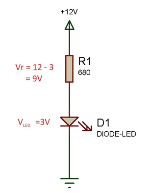
Power consumed by LED: 40mW (approx.)
Power consumed by resistor: 120mW
Power consumed by LED + Resistor: 160mW (approx.)
So, there is wastage of 120mW of power while using a series resistor and remember this only for a single LED. Then imagine how much power would be wasted for 18 such LEDs. Well although it’s not much but as engineers we are supposed to design an efficient system right?
P.S. – Adding a voltage regulator would have the same effect (Wastage of power through heat dissipation)
So what else can we do? The answer is: adding LEDs in series! Let’s see what happens when we add 3 LEDs in series and a resistor to it.
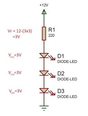
Power consumed by each LED: 41mW (approx.)
Power consumed by resistor: 41mW
Power consumed by 3 LEDs + Resistor: 164mW
So we have successfully reduced the power wasted by almost 80mW. But still as engineers we aren’t satisfied are we?
Eliminating the Resistors
The power given to LEDs must be limited which is usually done by resistors or voltage regulator but what else can do that? The answer is Pulse Width Modulation.
PWM is widely used in systems nowadays to control the power going to a particular system. It is just like switching ON-OFF the power to the system but doing it so rapidly that you don’t feel the change. Instead you feel the reduction in power.
So we’ll give our LEDs 12V power supply but using PWM we’ll bring the average power given to it over a cycle to 10V.
Here the Darlington array IC works as a switch and the 555 Timer produces the PWM signal used to rapidly ON-OFF the Darlington array.
Soldering:
Part 1: LEDs

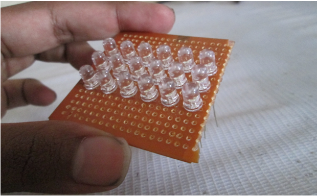
Take a small PCB and 18 white LEDs

Arrange them in threes, making 6 columns. Once you are satisfied by the positions and spacing between LEDs, mark their positions using a marker.
Now remove all the LEDs and start soldering column by column i.e., three at a time.
Now bend the negative lead of top LED and positive lead of middle LED towards each other and similarly negative lead of middle LED and positive lead of bottom LED towards each other.
Then solder them carefully.

Do the same for the other 5 columns also. Then start bending the positive leads of all top LEDs towards each other.

Now solder these terminals since all the columns would be connected to the same +ve end of the power supply.
This is how it looks once everything is done.

Top view of the PCB
Remember: While soldering, at each step check if the joints are done correctly and if the LED is working using a multimeter’s continuity feature. This way you can correct the errors in the circuit easily and also replace the LED if any are damaged.
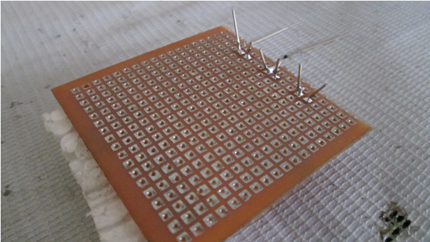
Part 2: Circuit
Take another small PCB. Since soldering ICs directly onto PCB is risky, I’m using an 8 pin bas and an 18 pin base for 555 Timer and ULN2803 ICs. Position the bases to see if there is enough spacing for other components.
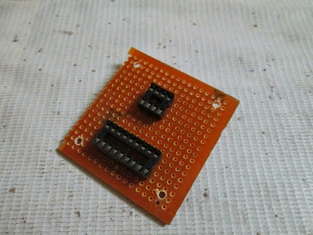
Once you are satisfied, start soldering the bases onto the PCB.

After the bases, start adding the components one by one.

Note: Don’t add the potentiometer right now.
Once the circuit is done, it’s time to combine the circuit with the LED board. For this, cut 6 equal pieces of wires and start soldering one end to the negative leads of each bottom LED.

Now solder the other end of these 6 wires to the pins 13 to 18 of the base.


Now solder two wires for the power supply and also a wire connecting the +ve terminal of the top LEDs to the +ve line on the circuit board.

Now it is time for adding the potentiometer. Solder two wires from the board (one from R2 resistor and other from pin 6 of 555 Timer) for connecting the potentiometer. Hook it up and test the light by adding power supply.

The lights should turn ON and when you adjust the POT value, the LEDs brightness should change now. If not, then you went wrong somewhere.

Congratulations! You are done with the circuit and soldering part. But still it doesn’t look like a lamp does it?
The next step is to find a good enclosure for our circuit to fit in nicely. I found a transparent box suitable for it.

Now I tested by putting inside the box and still get enough light from the circuit and so I’ve decided to put the LED board also inside only. If you have got an opaque enclosure then you would have to cut a rectangular slot in it to pop out the LED board.

We need to make two holes in the box, one for the potentiometer knob and, other for the power line.
Fix the pot using the nut given with it.

Make the other hole and then put all the circuit and now solder the wires of the potentiometer. Connect the power supply and you are ready to go. The finished setup looks like this

Ever wanted to make your own table lamp? If yes then you have come to the right tutorial! This project shows you how to make table lamp using a bunch of LEDs and 555 Timer circuit.
Components Required
1. Power supply 12V/1A
2. 5mm white LEDs X 18
3. 555 Timer IC
4. ULN2803 Darlington array IC
5. Resistor 4.7k,10k,680E
6. Potentiometer 100k
7. Capacitors 0.1uF X 2, 10uF electrolytic
8. Diode 1N914
9. Two small PCBs
Designing
Our first problem is that we can’t give 12V directly to an LED which would simply burn it. Well you may say that adding a series resistor would solve that problem but let’s see what happens when we do that.
Power consumed by LED: 40mW (approx.)
Power consumed by resistor: 120mW
Power consumed by LED + Resistor: 160mW (approx.)
So, there is wastage of 120mW of power while using a series resistor and remember this only for a single LED. Then imagine how much power would be wasted for 18 such LEDs. Well although it’s not much but as engineers we are supposed to design an efficient system right?
P.S. – Adding a voltage regulator would have the same effect (Wastage of power through heat dissipation)
So what else can we do? The answer is: adding LEDs in series! Let’s see what happens when we add 3 LEDs in series and a resistor to it.
Power consumed by each LED: 41mW (approx.)
Power consumed by resistor: 41mW
Power consumed by 3 LEDs + Resistor: 164mW
So we have successfully reduced the power wasted by almost 80mW. But still as engineers we aren’t satisfied are we?
Eliminating the Resistors
The power given to LEDs must be limited which is usually done by resistors or voltage regulator but what else can do that? The answer is Pulse Width Modulation.
PWM is widely used in systems nowadays to control the power going to a particular system. It is just like switching ON-OFF the power to the system but doing it so rapidly that you don’t feel the change. Instead you feel the reduction in power.
So we’ll give our LEDs 12V power supply but using PWM we’ll bring the average power given to it over a cycle to 10V.
Here the Darlington array IC works as a switch and the 555 Timer produces the PWM signal used to rapidly ON-OFF the Darlington array.
Soldering:
Part 1: LEDs
Take a small PCB and 18 white LEDs
Arrange them in threes, making 6 columns. Once you are satisfied by the positions and spacing between LEDs, mark their positions using a marker.
Now remove all the LEDs and start soldering column by column i.e., three at a time.
Now bend the negative lead of top LED and positive lead of middle LED towards each other and similarly negative lead of middle LED and positive lead of bottom LED towards each other.
Then solder them carefully.
Do the same for the other 5 columns also. Then start bending the positive leads of all top LEDs towards each other.
Now solder these terminals since all the columns would be connected to the same +ve end of the power supply.
This is how it looks once everything is done.
Top view of the PCB
Remember: While soldering, at each step check if the joints are done correctly and if the LED is working using a multimeter’s continuity feature. This way you can correct the errors in the circuit easily and also replace the LED if any are damaged.
Part 2: Circuit
Take another small PCB. Since soldering ICs directly onto PCB is risky, I’m using an 8 pin bas and an 18 pin base for 555 Timer and ULN2803 ICs. Position the bases to see if there is enough spacing for other components.
Once you are satisfied, start soldering the bases onto the PCB.
After the bases, start adding the components one by one.
Note: Don’t add the potentiometer right now.
Once the circuit is done, it’s time to combine the circuit with the LED board. For this, cut 6 equal pieces of wires and start soldering one end to the negative leads of each bottom LED.
Now solder the other end of these 6 wires to the pins 13 to 18 of the base.
Now solder two wires for the power supply and also a wire connecting the +ve terminal of the top LEDs to the +ve line on the circuit board.
Now it is time for adding the potentiometer. Solder two wires from the board (one from R2 resistor and other from pin 6 of 555 Timer) for connecting the potentiometer. Hook it up and test the light by adding power supply.
The lights should turn ON and when you adjust the POT value, the LEDs brightness should change now. If not, then you went wrong somewhere.
Congratulations! You are done with the circuit and soldering part. But still it doesn’t look like a lamp does it?
The next step is to find a good enclosure for our circuit to fit in nicely. I found a transparent box suitable for it.
Now I tested by putting inside the box and still get enough light from the circuit and so I’ve decided to put the LED board also inside only. If you have got an opaque enclosure then you would have to cut a rectangular slot in it to pop out the LED board.
We need to make two holes in the box, one for the potentiometer knob and, other for the power line.
Fix the pot using the nut given with it.
Make the other hole and then put all the circuit and now solder the wires of the potentiometer. Connect the power supply and you are ready to go. The finished setup looks like this
This article was published by me on EngineersGarage