
Introduction
Digital equipments have rapidly replaced Analog equipments in the long run. Well that is because the former has lot of advantages over the latter. But do you miss those retro style analog measuring instruments? Those pointy indicators and graduated scales? Well I do and so have decided to build one with the “modern” parts. This article will show you how to make a Retro Style D.C. Voltmeter which can measure in range of 0-30V.

Components Required
1. ATMega16 development board
2. Servo motor with servo horn
3. Resistors
4. Cardboard / Plastic box
5. Cardboard sheet
6. A Needle/ Old pen
Concept of Voltmeter and Voltage divider Design Equation
We all know that ATMega16 (in fact any) microcontroller cannot bear more than 5volts and you would end up damaging its pins if you try to apply more than 5volts to it. But we need to make the instrument capable of measuring at least up to 30 volts to call it as a voltmeter! And that’s where the concept of voltage divider circuit comes into play. Once you understand this concept, you can build voltmeter of any range.
Basically, voltage divider is a circuit used to get a fixed fraction of input voltage as an output voltage. Take a look at the diagram below

Here R1 and R2 are the resistors and Vin is the input voltage. The output voltage Vout is given as:
Vout = Vin X R2/(R1 + R2) . . . . . . . . . . . . . . . (1)
We choose the resistor values based on our requirements. Like say now our maximum voltage to be measured is 30V but we can only give up to 5V to our controller.
So here maximum Vin = 30V and maximum Vout = 5V
Substituting in equation (1) and on solving, we get
R1:R2 = 5 : 1
So we can take R1= 5kΩ and R2=1kΩ
You can design voltmeter of any range using the above equation.
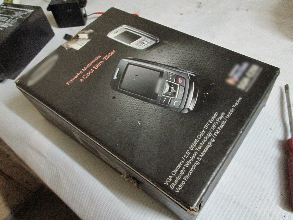
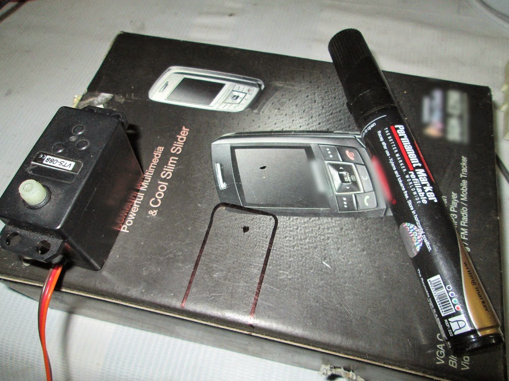
Making the Box and Scale
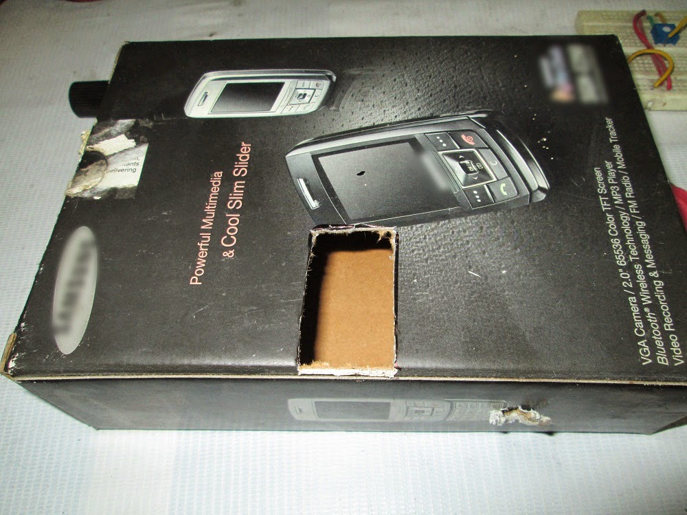
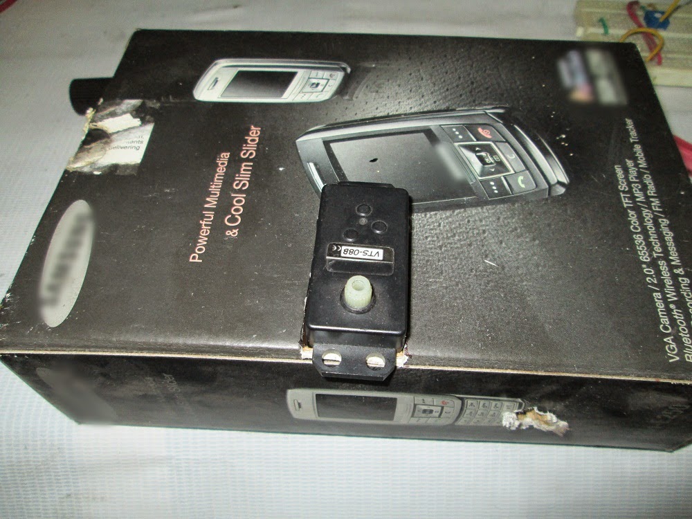
-First take a cardboard/ plastic box and cut a rectangular hole to fit in the servo motor.
-Now add another layer of cardboard sheet to cover up the servo exposing only the rotating part of it. Download the template image given below and take a printout of it on an A4 sheet (landscape). Stick it onto the cardboard sheet neatly. Make sure you align the printout correctly.

-Now take another part of card board piece and cut it in shape of an arrow mark. Then make a hole at the end of the arrow so that it can be fixed to servo axle.
OR
Simply take a needle/ pointy object and attach it to the servo horn and you are good to go!
Servo Working Principle:
The image below will give you a quick review on Servo motor working principle. You can get more details about the working principle here: “http://www.engineersgarage.com/contribution/expert/servo-motor-control-using-555-timer-ic”
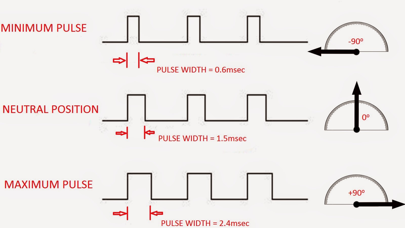
Servo motor is capable of rotating 180 degrees, but here for our convenience we are using only 150o span (-90 to +60 degrees) so that we get a resolution of 5o/volt (i.e. 150o/30V)
Code Explanation
Well the code is pretty simple and straight forward.
- Initialize the 16 bit ADC mode of the controller
- Initialize the Pulse Width Modulation function for the servo control
- Enter an infinite loop
- If PC0 goes low then move the pointer to maximum deflection position and come back to original position
- Read the voltage level at ADC1, convert it into a 16-bit discreet value (0 to 1023) and store it in a variable “val”.
- Divide the value at “val” by 1024 and then multiply it with 30. This gives you the original applied voltage value.
- Now adjust the servo angle according to the original applied voltage.
Conversion Process Example
-Let us say that we applied some input voltage Vin= 24V to the system
-Now from the design equation the output voltage of voltage divider circuit can be calculated. Here the output would be 4V which is the input to the ADC pin of microcontroller
-The controller would covert the analog value (0-5V) into a discreet value of range 0-1023. In this case the value would be around 819.
-Next, this discreet value is again converted into the original input voltage range which is 0-30V through programming. Here the value obtained would be 23.99 which is almost equal to 24V!
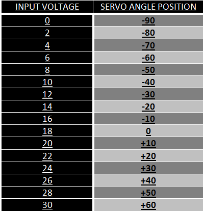
-Now the obtained value is used to set the angle of the servo motor. The voltage range of 0-30V is scaled to 0-150o range giving us a resolution of 0.2V/degree

Initial Setup:
-Dump the code into the controller and connect everything together.
-Connect nothing to the input. Now the voltage applied to the system is zero so fix the pointer to the servo axle such that the needle coincides with “0” mark on the scale.
-Now press the TEST button and you should see the pointer moving to maximum deflection point, i.e. to the “30” mark. After few seconds it will go to the zero point.
Troubleshooting:
Case 1: If there is deflection of 150o but the pointer doesn’t coincide with 0 and 30 mark.
Error: The pointer is not placed correctly on the axle. Adjust the pointer position by removing from servo axle and putting it back properly.
Case 2: Deflection produced when TEST button is pressed is more or less than 150o (i.e. the pointer doesn’t coincide with 30th mark.)
Error: There is something wrong in the OCR1A value. Look into your servo motor’s datasheet to find out the pulse width for the standard angles.
Case 3: The pointer keeps on fluctuating.
Error: The external voltage which you are measuring may contain some noise or AC components. Remember that the controller needs some time to convert the analog input voltage into a digital value.
OR
Check the power supply to the system. Note that servo draws large amount of current.
Note
Please do not expect this project to replace a commercial digital voltmeter. Although it shows the voltage value correctly up to a certain extent, it is not as accurate as a commercial voltmeter.
This article was published by me on EngineersGarage
Digital equipments have rapidly replaced Analog equipments in the long run. Well that is because the former has lot of advantages over the latter. But do you miss those retro style analog measuring instruments? Those pointy indicators and graduated scales? Well I do and so have decided to build one with the “modern” parts. This article will show you how to make a Retro Style D.C. Voltmeter which can measure in range of 0-30V.
Components Required
1. ATMega16 development board
2. Servo motor with servo horn
3. Resistors
4. Cardboard / Plastic box
5. Cardboard sheet
6. A Needle/ Old pen
Concept of Voltmeter and Voltage divider Design Equation
We all know that ATMega16 (in fact any) microcontroller cannot bear more than 5volts and you would end up damaging its pins if you try to apply more than 5volts to it. But we need to make the instrument capable of measuring at least up to 30 volts to call it as a voltmeter! And that’s where the concept of voltage divider circuit comes into play. Once you understand this concept, you can build voltmeter of any range.
Basically, voltage divider is a circuit used to get a fixed fraction of input voltage as an output voltage. Take a look at the diagram below
Here R1 and R2 are the resistors and Vin is the input voltage. The output voltage Vout is given as:
Vout = Vin X R2/(R1 + R2) . . . . . . . . . . . . . . . (1)
We choose the resistor values based on our requirements. Like say now our maximum voltage to be measured is 30V but we can only give up to 5V to our controller.
So here maximum Vin = 30V and maximum Vout = 5V
Substituting in equation (1) and on solving, we get
R1:R2 = 5 : 1
So we can take R1= 5kΩ and R2=1kΩ
You can design voltmeter of any range using the above equation.
Making the Box and Scale
-First take a cardboard/ plastic box and cut a rectangular hole to fit in the servo motor.
-Now add another layer of cardboard sheet to cover up the servo exposing only the rotating part of it. Download the template image given below and take a printout of it on an A4 sheet (landscape). Stick it onto the cardboard sheet neatly. Make sure you align the printout correctly.
-Now take another part of card board piece and cut it in shape of an arrow mark. Then make a hole at the end of the arrow so that it can be fixed to servo axle.
OR
Simply take a needle/ pointy object and attach it to the servo horn and you are good to go!
Servo Working Principle:
The image below will give you a quick review on Servo motor working principle. You can get more details about the working principle here: “http://www.engineersgarage.com/contribution/expert/servo-motor-control-using-555-timer-ic”
Servo motor is capable of rotating 180 degrees, but here for our convenience we are using only 150o span (-90 to +60 degrees) so that we get a resolution of 5o/volt (i.e. 150o/30V)
Code Explanation
Well the code is pretty simple and straight forward.
- Initialize the 16 bit ADC mode of the controller
- Initialize the Pulse Width Modulation function for the servo control
- Enter an infinite loop
- If PC0 goes low then move the pointer to maximum deflection position and come back to original position
- Read the voltage level at ADC1, convert it into a 16-bit discreet value (0 to 1023) and store it in a variable “val”.
- Divide the value at “val” by 1024 and then multiply it with 30. This gives you the original applied voltage value.
- Now adjust the servo angle according to the original applied voltage.
Conversion Process Example
-Let us say that we applied some input voltage Vin= 24V to the system
-Now from the design equation the output voltage of voltage divider circuit can be calculated. Here the output would be 4V which is the input to the ADC pin of microcontroller
-The controller would covert the analog value (0-5V) into a discreet value of range 0-1023. In this case the value would be around 819.
-Next, this discreet value is again converted into the original input voltage range which is 0-30V through programming. Here the value obtained would be 23.99 which is almost equal to 24V!
-Now the obtained value is used to set the angle of the servo motor. The voltage range of 0-30V is scaled to 0-150o range giving us a resolution of 0.2V/degree
Initial Setup:
-Dump the code into the controller and connect everything together.
-Connect nothing to the input. Now the voltage applied to the system is zero so fix the pointer to the servo axle such that the needle coincides with “0” mark on the scale.
-Now press the TEST button and you should see the pointer moving to maximum deflection point, i.e. to the “30” mark. After few seconds it will go to the zero point.
Troubleshooting:
Case 1: If there is deflection of 150o but the pointer doesn’t coincide with 0 and 30 mark.
Error: The pointer is not placed correctly on the axle. Adjust the pointer position by removing from servo axle and putting it back properly.
Case 2: Deflection produced when TEST button is pressed is more or less than 150o (i.e. the pointer doesn’t coincide with 30th mark.)
Error: There is something wrong in the OCR1A value. Look into your servo motor’s datasheet to find out the pulse width for the standard angles.
Case 3: The pointer keeps on fluctuating.
Error: The external voltage which you are measuring may contain some noise or AC components. Remember that the controller needs some time to convert the analog input voltage into a digital value.
OR
Check the power supply to the system. Note that servo draws large amount of current.
Note
Please do not expect this project to replace a commercial digital voltmeter. Although it shows the voltage value correctly up to a certain extent, it is not as accurate as a commercial voltmeter.
This article was published by me on EngineersGarage