
Introduction
Fastest Finger first circuit is basically used in quiz type games where the reaction speed of a participant is significant. The circuit enables us to identify who responded first to the question by triggering a visual and audio indication.
Components Required
1. 1 x ATMega16 development board
2. 1 x Seven Segment display
3. 8 x 330 ohms Resistor
4. 9 x Momentary Switches (8 Teams + 1 Reset switch)
5. 1 x Buzzer
6. 1 x BC547 Transistor
Description
The circuit uses a buzzer to produce the audio signal and a seven segment display for visual indication. The display shows the corresponding team number which pressed the buzzer first. The brain of this circuit is an ATMega16 microcontroller which can run at a maximum speed of 16MHz and so there will be no question of clash between any two contestants until and unless their reaction time was same in order of microseconds which is impossible.
Seven Segment Display
It consists of seven LEDs named a, b, c, d, e, f and g which when turned ON or OFF in a particular pattern displays a decimal number from 0 to 9 or alphabets A to F. The seven LEDs either have a common cathode or common anode configuration in order to reduce the number of pins.
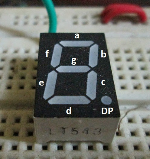
Pin Diagram for the two types are as follows

The table below shows the number/ alphabet displayed and its corresponding pattern.
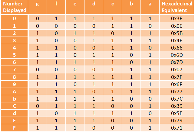
The hexadecimal value will be useful for us while interfacing the display with a microcontroller.
Note that the lowest pin number of the port (usually Px0) is connected to “a” pin and the highest (Px7) to “g” pin (Here x= A/B/C/D)
Use of Transistor
Microcontrollers are usually not capable of driving a Buzzer directly from its output pin and so we use a small circuit to amplify the signal coming from the output pin of the controller to drive the buzzer.
Note: Don’t try to connect the buzzer directly to the controller’s output pin. It may damage the controller permanently!
Code Explanation:
-Initialize the input and output ports (PORTA as input, PORTD as output,PC0 as output for BUZZER and PB0 as input for RESET)
-Enter into an infinite loop.
-Check if any button connected to PORTA is pressed.
-If pressed, stored the position of button pressed in a variable named ‘val’ and then send the value through display(val) function.
-Turn ON the buzzer and display the number corresponding to the ‘val’ on the seven segment display.
-Wait for the RESET button to be pressed. If pressed then turn OFF the BUZZER and reset the seven segment display also.
-Go back to the infinite loop and keep checking for the button press
Note
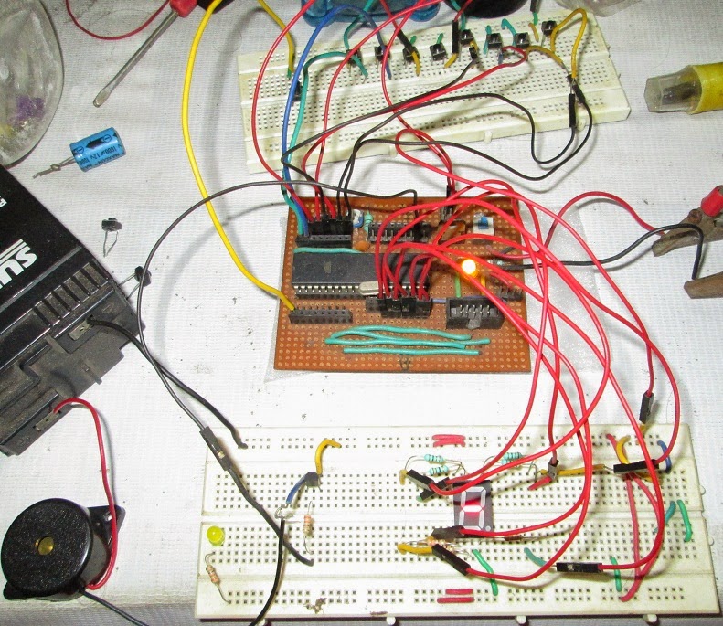
I have used small tactile button switches on a breadboard for demo purpose but if you are actually making the circuit for a contest you may want to replace the button switch with big ones like the one shown below
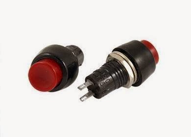
These are bit expensive when compared to the small button switches but are more reliable and also look professional!
Here is a demo video:
Fastest Finger first circuit is basically used in quiz type games where the reaction speed of a participant is significant. The circuit enables us to identify who responded first to the question by triggering a visual and audio indication.
Components Required
1. 1 x ATMega16 development board
2. 1 x Seven Segment display
3. 8 x 330 ohms Resistor
4. 9 x Momentary Switches (8 Teams + 1 Reset switch)
5. 1 x Buzzer
6. 1 x BC547 Transistor
Description
The circuit uses a buzzer to produce the audio signal and a seven segment display for visual indication. The display shows the corresponding team number which pressed the buzzer first. The brain of this circuit is an ATMega16 microcontroller which can run at a maximum speed of 16MHz and so there will be no question of clash between any two contestants until and unless their reaction time was same in order of microseconds which is impossible.
Seven Segment Display
It consists of seven LEDs named a, b, c, d, e, f and g which when turned ON or OFF in a particular pattern displays a decimal number from 0 to 9 or alphabets A to F. The seven LEDs either have a common cathode or common anode configuration in order to reduce the number of pins.
Pin Diagram for the two types are as follows
The table below shows the number/ alphabet displayed and its corresponding pattern.
The hexadecimal value will be useful for us while interfacing the display with a microcontroller.
Note that the lowest pin number of the port (usually Px0) is connected to “a” pin and the highest (Px7) to “g” pin (Here x= A/B/C/D)
Use of Transistor
Microcontrollers are usually not capable of driving a Buzzer directly from its output pin and so we use a small circuit to amplify the signal coming from the output pin of the controller to drive the buzzer.
Note: Don’t try to connect the buzzer directly to the controller’s output pin. It may damage the controller permanently!
Code Explanation:
-Initialize the input and output ports (PORTA as input, PORTD as output,PC0 as output for BUZZER and PB0 as input for RESET)
-Enter into an infinite loop.
-Check if any button connected to PORTA is pressed.
-If pressed, stored the position of button pressed in a variable named ‘val’ and then send the value through display(val) function.
-Turn ON the buzzer and display the number corresponding to the ‘val’ on the seven segment display.
-Wait for the RESET button to be pressed. If pressed then turn OFF the BUZZER and reset the seven segment display also.
-Go back to the infinite loop and keep checking for the button press
Note
I have used small tactile button switches on a breadboard for demo purpose but if you are actually making the circuit for a contest you may want to replace the button switch with big ones like the one shown below
These are bit expensive when compared to the small button switches but are more reliable and also look professional!
Here is a demo video:
This article was published by me on EngineersGarage