
Introduction
Well as the Halloween is coming close I thought why not show you how to make an interactive electronic Halloween prop. All we need is a PIR sensor, an arduino/ ATMega8 board and couple of other electronic components to make this Haunted Post box.
Components Required
1. Arduino/ ATmega8 / ATmega16 board
2. 1 x PIR Sensor
3. 1 x Servo Motor (Medium Torque) with servo horn
4. 1 x BC547 (or any other equivalent) Transistor
5. 2 x Resistors 330 ohms
6. 1 x LED
7. 4 x AA Battery Holder
8. 4 x AA Batteries
9. A Plastic/ Carton box
10. Nuts, bolts, spacers, etc.
11. Solid Wires
12. Plastic Rulers
13. Female Jumper wires
Tools Required
1. Soldering machine, De-Soldering wick, Flux, Soldering wire
2. PCB drilling machine/ Hand Drill
3. Screwdriver, Cutter, Wire stripper
4. Insulation tape
5. Digital Multimeter
What The Prop Does?
Basically a scary element pops out of the post box as soon as the PIR sensor senses a human nearby the door step. It stays out for a while and again goes back into the post-box and stays there till the next victim comes close. The scary element is of your choice. It can be a plastic skull or a monster mask or a toy hand or anything which scares people when they see it suddenly. Be creative! And use your own imagination.
Circuit Explanation
The most important part of the circuit is the PIR (Passive Infra-Red) sensor. These sensors basically measure the Infrared light radiated by an object present in its field. All living creatures (and objects) with a temperature above absolute zero (which is 0 Kelvin or -273oC) emit heat energy in form of radiation. The PIR sensors are tuned in such a way that they detect only the radiation emitted by human beings.
To know more about how it works go to this link: http://www.engineersgarage.com/insight/how-motion-pir-sensor-works
Now this sensor would be used to detect our targets coming near to our door steps and trigger the scaring mechanism.
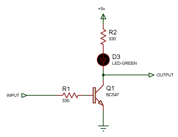
Amplifier Circuit
Since the output coming from a PIR sensor is quite weak, we use a transistor to amplify the output signal. You can either solder the circuit onto a small PCB or directly solder the pins of the components according to the circuit diagram. When I say to connect the output of PIR sensor to the microcontroller pin, it means you need to connect the output of this amplifier.
Mechanism
Since the scary element needs to pop out of the box and go back into it, which is a linear motion, we can’t simply use just a DC geared motor or a servo motor. We will need a crank type mechanism to convert the circular motion of the motor into a linear motion for the scary element to work.
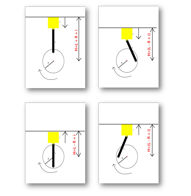
The length ‘L’ and radius ‘R’ should be chosen carefully based on the height of the scary element you are using.
The maximum height the element’s bottom can reach is H= (L + R + i) and
The minimum height is H= (L – R + i)
Points to Remember:
-> The height of the element should be less than ‘2xR’ or else it will not completely fit into to the post box in minimum position.
-> The length ‘L’ should be slightly more than the diameter (2xR) of the wheel.
Diagrammatic Explanation

Working
The post box would be very normal when there is no one around it. Initially the servo axle is at 0o, but when a person comes in front of the PIR sensor, the servo rotates to 180o and the following happens.

And after a period of time say five seconds, the element goes back into the box and the lid gets shut automatically due to gravity, making the haunted post-box look like a normal one again (by this time the victim would have ran away and so we need to hide the surprise from next target).

Code Explanation
The code is pretty simple and straight forward. I have attached the code for most commonly used development boards (ATmega8 dev. Board & ATmega16 dev. board) .You can easily modify the code to work with arduino also.
-Initialize the timers for non inverted Pulse Width Modulation and fast PWM mode.
-Set the time period = 20ms (frequency = 50Hz)
-Configure PD5 of PORTD as output (PB1 in ATmega8). This is where the Servo motor is connected.
-Configure the first pin PA1 of PORTA as input (PC0 in ATmega8/ digital pin 14 in arduino) and set it to logic high state. This is where the output of PIR signal is connected to (through an amplifier circuit)
-Enter an infinite loop.
-If PA1 goes low, change the servo angle to 180o , wait for few seconds and change the angle back to 0o
Making of the box and mechanism
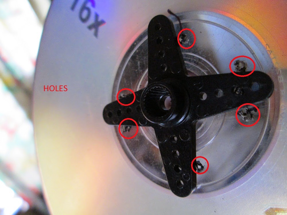
I’m using an old CD and a couple of plastic rulers to make the crank mechanism.
First we attach the servo horn to the CD by making some holes on the CD and using couple of solid wires. Use the necessary tools.


Then we take two pieces of plastic ruler and make holes in them so that we can attach them.

Use few bolts and lot of nuts to make the joints. If the holes are too big for the screws, use some plastic or PCB pieces to fix them.


Dump the program into the controller, connect the setup as per the circuit diagram and attach the wheel (CD in my case) to the servo. Now test the mechanism and see if it runs works smoothly.
Note: For testing you can connect a tactile switch to the input pin of the controller (and other end of switch to ground) instead of PIR sensor. This is because PIR sensor will continuously sense you so you cannot sit near and test the circuit.
http://youtu.be/DWAbZOihGIM
Once you have tested the mechanism next you need to find a suitable box (cardboard or plastic) to put it in. Remember to cut the slot inside the box as shown in the drawings.
http://youtu.be/DvCEAEZYahw
Final Touches
Well as the title says, the prop is supposed to look like a post-box remember? Post boxes look different in different place and so it’s up to you to find out how they look in your region and make the prop look similar to that.
Well as the Halloween is coming close I thought why not show you how to make an interactive electronic Halloween prop. All we need is a PIR sensor, an arduino/ ATMega8 board and couple of other electronic components to make this Haunted Post box.
Components Required
1. Arduino/ ATmega8 / ATmega16 board
2. 1 x PIR Sensor
3. 1 x Servo Motor (Medium Torque) with servo horn
4. 1 x BC547 (or any other equivalent) Transistor
5. 2 x Resistors 330 ohms
6. 1 x LED
7. 4 x AA Battery Holder
8. 4 x AA Batteries
9. A Plastic/ Carton box
10. Nuts, bolts, spacers, etc.
11. Solid Wires
12. Plastic Rulers
13. Female Jumper wires
Tools Required
1. Soldering machine, De-Soldering wick, Flux, Soldering wire
2. PCB drilling machine/ Hand Drill
3. Screwdriver, Cutter, Wire stripper
4. Insulation tape
5. Digital Multimeter
What The Prop Does?
Basically a scary element pops out of the post box as soon as the PIR sensor senses a human nearby the door step. It stays out for a while and again goes back into the post-box and stays there till the next victim comes close. The scary element is of your choice. It can be a plastic skull or a monster mask or a toy hand or anything which scares people when they see it suddenly. Be creative! And use your own imagination.
Circuit Explanation
The most important part of the circuit is the PIR (Passive Infra-Red) sensor. These sensors basically measure the Infrared light radiated by an object present in its field. All living creatures (and objects) with a temperature above absolute zero (which is 0 Kelvin or -273oC) emit heat energy in form of radiation. The PIR sensors are tuned in such a way that they detect only the radiation emitted by human beings.
To know more about how it works go to this link: http://www.engineersgarage.com/insight/how-motion-pir-sensor-works
Now this sensor would be used to detect our targets coming near to our door steps and trigger the scaring mechanism.
Amplifier Circuit
Since the output coming from a PIR sensor is quite weak, we use a transistor to amplify the output signal. You can either solder the circuit onto a small PCB or directly solder the pins of the components according to the circuit diagram. When I say to connect the output of PIR sensor to the microcontroller pin, it means you need to connect the output of this amplifier.
Mechanism
Since the scary element needs to pop out of the box and go back into it, which is a linear motion, we can’t simply use just a DC geared motor or a servo motor. We will need a crank type mechanism to convert the circular motion of the motor into a linear motion for the scary element to work.
The length ‘L’ and radius ‘R’ should be chosen carefully based on the height of the scary element you are using.
The maximum height the element’s bottom can reach is H= (L + R + i) and
The minimum height is H= (L – R + i)
Points to Remember:
-> The height of the element should be less than ‘2xR’ or else it will not completely fit into to the post box in minimum position.
-> The length ‘L’ should be slightly more than the diameter (2xR) of the wheel.
Diagrammatic Explanation
Working
The post box would be very normal when there is no one around it. Initially the servo axle is at 0o, but when a person comes in front of the PIR sensor, the servo rotates to 180o and the following happens.
And after a period of time say five seconds, the element goes back into the box and the lid gets shut automatically due to gravity, making the haunted post-box look like a normal one again (by this time the victim would have ran away and so we need to hide the surprise from next target).
Code Explanation
The code is pretty simple and straight forward. I have attached the code for most commonly used development boards (ATmega8 dev. Board & ATmega16 dev. board) .You can easily modify the code to work with arduino also.
-Initialize the timers for non inverted Pulse Width Modulation and fast PWM mode.
-Set the time period = 20ms (frequency = 50Hz)
-Configure PD5 of PORTD as output (PB1 in ATmega8). This is where the Servo motor is connected.
-Configure the first pin PA1 of PORTA as input (PC0 in ATmega8/ digital pin 14 in arduino) and set it to logic high state. This is where the output of PIR signal is connected to (through an amplifier circuit)
-Enter an infinite loop.
-If PA1 goes low, change the servo angle to 180o , wait for few seconds and change the angle back to 0o
Making of the box and mechanism
I’m using an old CD and a couple of plastic rulers to make the crank mechanism.
First we attach the servo horn to the CD by making some holes on the CD and using couple of solid wires. Use the necessary tools.
Then we take two pieces of plastic ruler and make holes in them so that we can attach them.
Use few bolts and lot of nuts to make the joints. If the holes are too big for the screws, use some plastic or PCB pieces to fix them.
Dump the program into the controller, connect the setup as per the circuit diagram and attach the wheel (CD in my case) to the servo. Now test the mechanism and see if it runs works smoothly.
Note: For testing you can connect a tactile switch to the input pin of the controller (and other end of switch to ground) instead of PIR sensor. This is because PIR sensor will continuously sense you so you cannot sit near and test the circuit.
http://youtu.be/DWAbZOihGIM
Once you have tested the mechanism next you need to find a suitable box (cardboard or plastic) to put it in. Remember to cut the slot inside the box as shown in the drawings.
http://youtu.be/DvCEAEZYahw
Final Touches
Well as the title says, the prop is supposed to look like a post-box remember? Post boxes look different in different place and so it’s up to you to find out how they look in your region and make the prop look similar to that.