
Introduction
Touch screens are two dimensional input devices. Nowadays most of the electronic gadgets use them. Laptops, smart phones, tablets and even some home appliances like washing machines & microwave ovens also use a touch screen nowadays.
Why Touch screens?
Touch screens are preferred over keypads because they need very little or no pressure to operate whereas the Keypads/ buttons need a minimum pressure to operate and our hands start aching after some time of continuous usage.
And one more great advantage in using a touch screens is that it enables us to make more room for the screen itself instead of wasting the space on the permanent keypad. And that’s the reason for our smart phone’s screens to become big enough to browse web pages also and still fit in our pockets.
Touch screens are of various types like Resistive, Capacitive, Surface Acoustic Wave (SAW), Infrared Grid, Optical Imaging, etc.
In this tutorial we’ll learn how to interface a 4-wire Resistive touch screen with ATmega16 microcontroller.
Components Required
1. ATMega16 development board
2. UART to USB converter or (UART to RS-232 converter + RS-232 to USB converter)
3. Touch Screen with connector
4. Few female to female jumper wires
5. Breadboard
6. 4 x 10k Resistors
Making a Connector
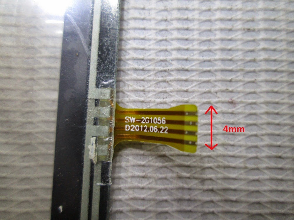
Before learning how to interface a touch screen we need to look into a problem. One of the biggest drawbacks of using a cheap touch screen is that they usually don’t come with the connector which is very much required to interface them with any kind of microcontroller development board. You can buy connectors online but in some cases they cost more than the touch screen itself. So I’ll show how to make break out board by soldering tiny wires onto the strip emerging from the touch screen.
Caution: Do the following procedure with your own risk. It does require some good soldering skills (not expert level but if this is your first time soldering then I advice not to do this by your own) since the strip emerging from the touch screen is very narrow.
Things Required
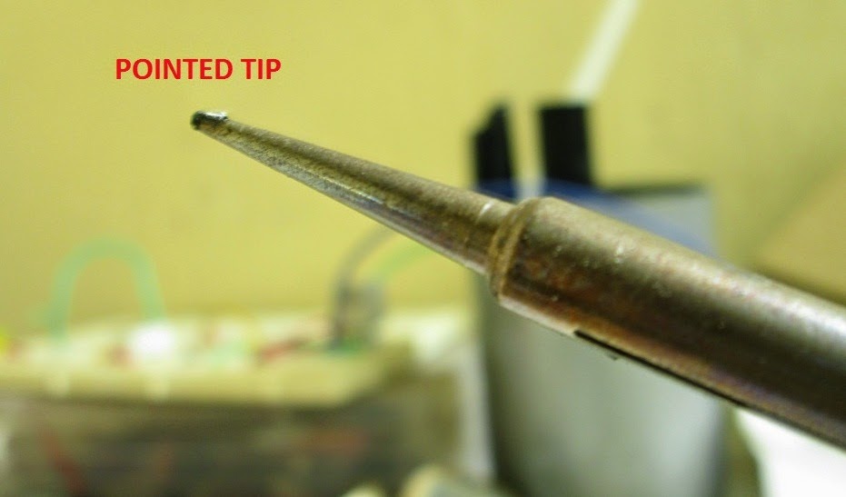
1. Soldering iron with pointed tip
2. Flux paste
3. Soldering wire
4. 4 Tiny Wires
5. Wire stripper
6. A small PCB
7. 4-pin Male Header
8. A Magnifying Glass
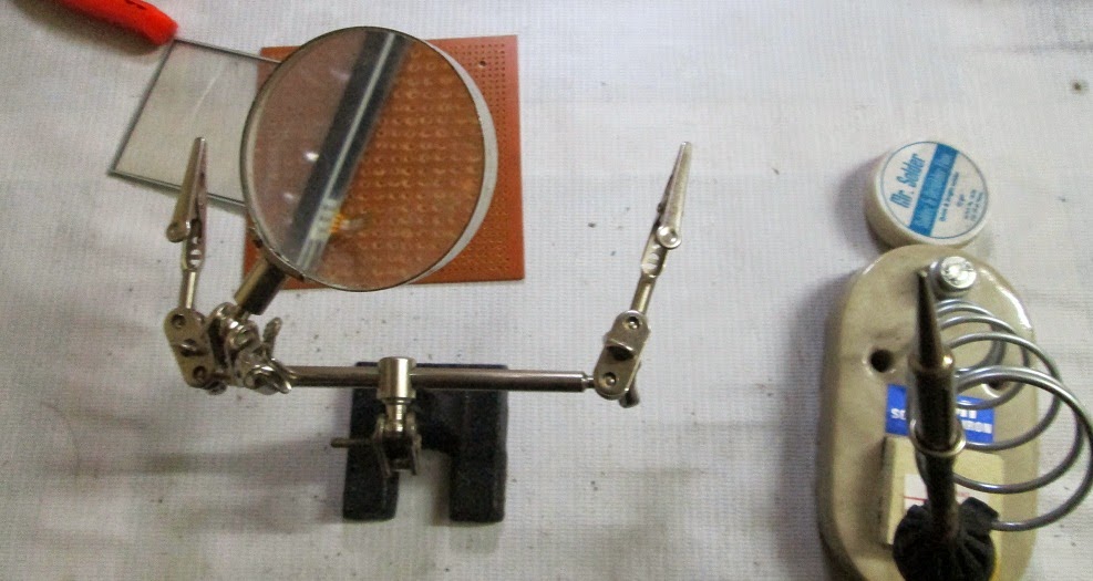
The Magnifying Glass is a must (unless you are a super human). I had a third hand PCB holder which had a good quality magnifying glass with 4X power so I used that.
Process
1. First apply some flux paste neatly on the touch screen strip.
2. Take some solder on the tip of the soldering iron and apply it on the strip.
Spread it evenly so that the solder gets attached only to the copper part of the strip and make sure none of the 4 is shorted.
3. Now strip the tiny wires so that a part of the copper wire is out. Then tin then neatly using the soldering iron.
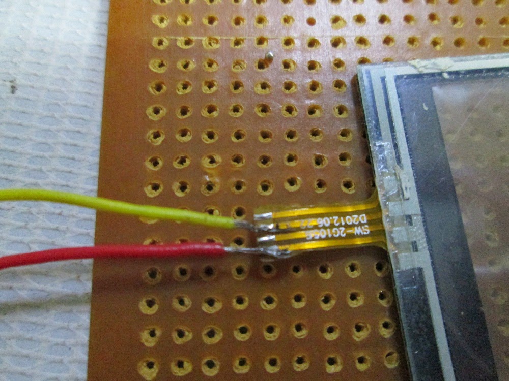
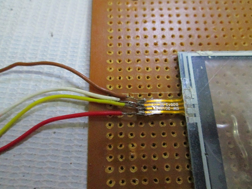
4. Then solder the wires one by one to the touch screen strip by putting the wire on the copper part of the strip (which has some solder now) and applying some heat gently using the solder iron.
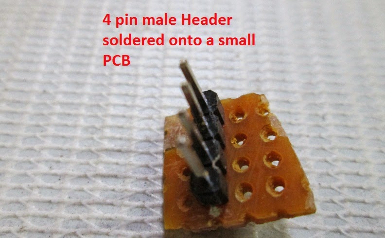
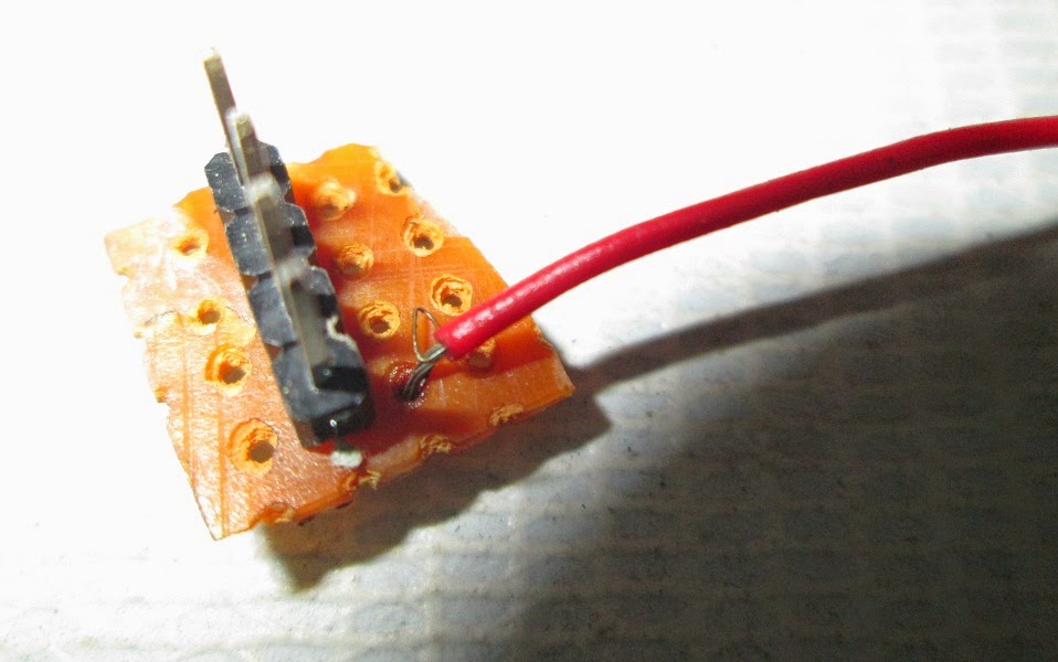
5. When you are done with that then solder the other end of the 4 wires to the small PCB along with the 4-pin male header, each wire to one pin.
Note: If you don’t want to do so much of soldering work then it is better to buy a touch screen with a readymade breakout board (highly recommended). Trust me it saves a lot of time and energy.
Readymade Connector
Even readymade connectors are not directly compatible with all touch screens. For example I bought a Nintendo touch screen and a breakout board compatible with it. But it still needs a modification to work properly.
Problem: Thickness of the ribbon cable (or simply the strip) emerging from the Nintendo touch screen is 0.1mm thick whereas the connector fits well only with cables which are at least 0.3mm thick.
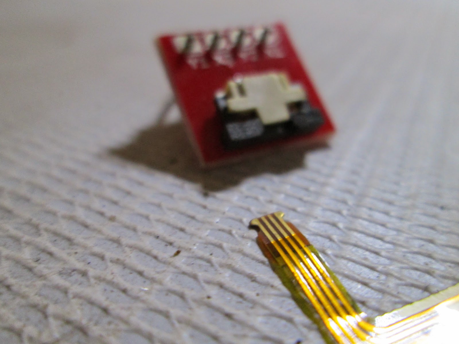
Solution: We add some insulation tape to the ribbon cable to make it thicker. Make sure you stick the tape on the back side of the strip where the copper part is not exposed and also cut the extra tape out or else the strip will not go inside the connector.
Next, you need to slightly slide out the black part of the breakout board connector. Insert the ribbon cable inside the connector and then slide back the black part to get a firm connection.
As the connector is ready, now we can go into the working and interfacing part.
How it works
Working of a Resistive touch screens can be understood by the below diagram.
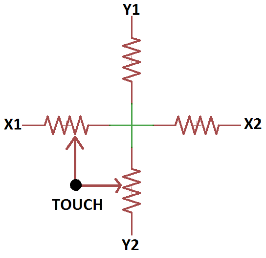
Your touch would actually create a variation in the resistance between two ends and that’s how the position of the touch is determined. Since directly measuring the resistance is not easy so we apply a fixed voltage (say 5 volts) between the two ends and, measure the outgoing voltage using ADC.
It is just like varying the voltage coming out of the potentiometer and measuring it. The only difference is that we use a knob in case of a potentiometer to vary the resistance and we use our touch in case of touch screens to vary the resistance.
The 4 wires (coming from the four ends) are connected to the 4 pins of PORTA of ATMega16
The table below shows the connection and state of each individual pin
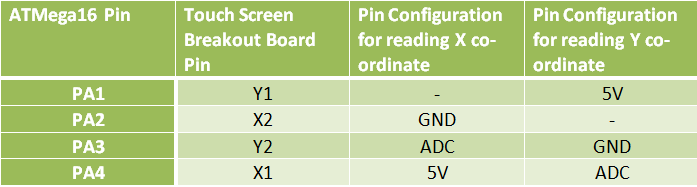
Note: As you can see from the table we just need two of the four pins to be connected to the ADC which is PORTA. Other two can be connected to any other pins of the controller but for making the code simpler I have connected them to the same port.
Code Explanation
-Map the 4 pins of PORTA in the following way using “#define”
#define y1 PA1
#define x2 PA2
#define y2 PA3
#define x1 PA4
-Initialize the USART and ADC functions of the microcontroller.
-Enter into an infinite while loop
-Configure x1 (PA4) & x2 (PA2) as outputs. Set x1 (PA4) to high (+5V) state and x2 (PA2) to low (GND) state.
-Read the analog voltage at y2 (PA3) using ReadADC(3) command. Store the discrete value in the variable “x”
-Configure y1 (PA1) & y2 (PA3) as outputs. Set y1 (PA1) to high (+5V) state and y2 (PA3) to low (GND) state.
-Read the analog voltage at x1 (PA4) using ReadADC(4) command. Store the discrete value in the variable “y”
-Transmit the co-ordinates in “x, y” format to the PC using WrCoord(x,y) function.
Looks very simple right? But it did take long time for me to develop it.
Setup Instructions:
1. You can either compile the code given using a suitable compiler like WINAVR with ATMEL STUDIO/AVR STUDIO or simply burn the “touchscrn.hex” file given below.
2. Plug in the converter using an USB cable. If you are connecting it for the first time then get the drivers installed and note down the COM port to which the converter is connected. Go to System Properties> Device Manager and look out for the converter by its name to see the COM port number. And also turn ON the development board.
3. Open the serial communication software in your PC/Laptop i.e. RealTerm/HyperTerminal.
Note: I’m using my own software.
4. If you are using RealTerm then go to the Port Tab and set it as follows.
Baud: 9600
Port: <The port where the Converter is connected to>
Data bits: 8
Parity: None
Stop bits: 1
Hardware Flow Control: None
Now you should start seeing some data on the computer screen. The co-ordinates will be in “x, y” format. When no touch is sensed the co-ordinates will be “0000, 0000” or very close to zero (usually less than 15)
Here is the video showing an example of how the values look like:
Touch screens are two dimensional input devices. Nowadays most of the electronic gadgets use them. Laptops, smart phones, tablets and even some home appliances like washing machines & microwave ovens also use a touch screen nowadays.
Why Touch screens?
Touch screens are preferred over keypads because they need very little or no pressure to operate whereas the Keypads/ buttons need a minimum pressure to operate and our hands start aching after some time of continuous usage.
And one more great advantage in using a touch screens is that it enables us to make more room for the screen itself instead of wasting the space on the permanent keypad. And that’s the reason for our smart phone’s screens to become big enough to browse web pages also and still fit in our pockets.
Touch screens are of various types like Resistive, Capacitive, Surface Acoustic Wave (SAW), Infrared Grid, Optical Imaging, etc.
In this tutorial we’ll learn how to interface a 4-wire Resistive touch screen with ATmega16 microcontroller.
Components Required
1. ATMega16 development board
2. UART to USB converter or (UART to RS-232 converter + RS-232 to USB converter)
3. Touch Screen with connector
4. Few female to female jumper wires
5. Breadboard
6. 4 x 10k Resistors
Making a Connector
Before learning how to interface a touch screen we need to look into a problem. One of the biggest drawbacks of using a cheap touch screen is that they usually don’t come with the connector which is very much required to interface them with any kind of microcontroller development board. You can buy connectors online but in some cases they cost more than the touch screen itself. So I’ll show how to make break out board by soldering tiny wires onto the strip emerging from the touch screen.
Caution: Do the following procedure with your own risk. It does require some good soldering skills (not expert level but if this is your first time soldering then I advice not to do this by your own) since the strip emerging from the touch screen is very narrow.
Things Required
1. Soldering iron with pointed tip
2. Flux paste
3. Soldering wire
4. 4 Tiny Wires
5. Wire stripper
6. A small PCB
7. 4-pin Male Header
8. A Magnifying Glass
The Magnifying Glass is a must (unless you are a super human). I had a third hand PCB holder which had a good quality magnifying glass with 4X power so I used that.
Process
1. First apply some flux paste neatly on the touch screen strip.
2. Take some solder on the tip of the soldering iron and apply it on the strip.
Spread it evenly so that the solder gets attached only to the copper part of the strip and make sure none of the 4 is shorted.
3. Now strip the tiny wires so that a part of the copper wire is out. Then tin then neatly using the soldering iron.
4. Then solder the wires one by one to the touch screen strip by putting the wire on the copper part of the strip (which has some solder now) and applying some heat gently using the solder iron.
5. When you are done with that then solder the other end of the 4 wires to the small PCB along with the 4-pin male header, each wire to one pin.
Note: If you don’t want to do so much of soldering work then it is better to buy a touch screen with a readymade breakout board (highly recommended). Trust me it saves a lot of time and energy.
Readymade Connector
Even readymade connectors are not directly compatible with all touch screens. For example I bought a Nintendo touch screen and a breakout board compatible with it. But it still needs a modification to work properly.
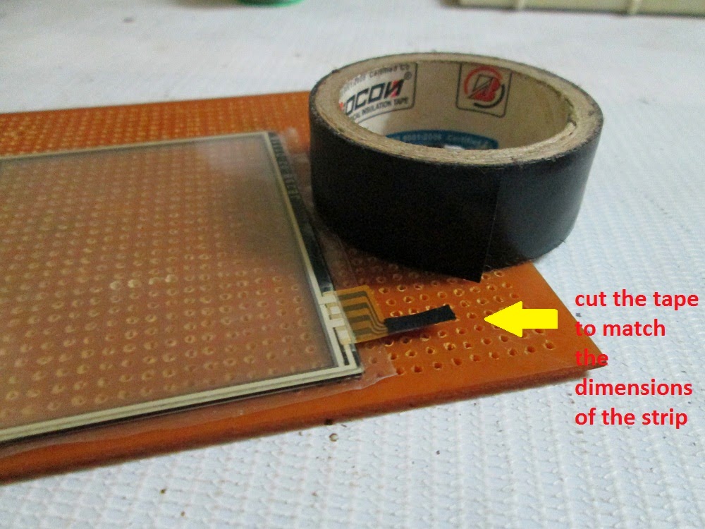
Problem: Thickness of the ribbon cable (or simply the strip) emerging from the Nintendo touch screen is 0.1mm thick whereas the connector fits well only with cables which are at least 0.3mm thick.
Solution: We add some insulation tape to the ribbon cable to make it thicker. Make sure you stick the tape on the back side of the strip where the copper part is not exposed and also cut the extra tape out or else the strip will not go inside the connector.
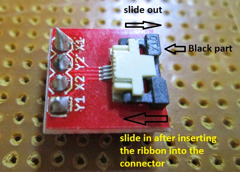
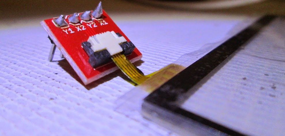
Next, you need to slightly slide out the black part of the breakout board connector. Insert the ribbon cable inside the connector and then slide back the black part to get a firm connection.
As the connector is ready, now we can go into the working and interfacing part.
How it works
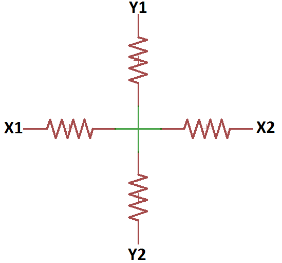
Working of a Resistive touch screens can be understood by the below diagram.
Your touch would actually create a variation in the resistance between two ends and that’s how the position of the touch is determined. Since directly measuring the resistance is not easy so we apply a fixed voltage (say 5 volts) between the two ends and, measure the outgoing voltage using ADC.
It is just like varying the voltage coming out of the potentiometer and measuring it. The only difference is that we use a knob in case of a potentiometer to vary the resistance and we use our touch in case of touch screens to vary the resistance.
The 4 wires (coming from the four ends) are connected to the 4 pins of PORTA of ATMega16
The table below shows the connection and state of each individual pin
Note: As you can see from the table we just need two of the four pins to be connected to the ADC which is PORTA. Other two can be connected to any other pins of the controller but for making the code simpler I have connected them to the same port.
Code Explanation
-Map the 4 pins of PORTA in the following way using “#define”
#define y1 PA1
#define x2 PA2
#define y2 PA3
#define x1 PA4
-Initialize the USART and ADC functions of the microcontroller.
-Enter into an infinite while loop
-Configure x1 (PA4) & x2 (PA2) as outputs. Set x1 (PA4) to high (+5V) state and x2 (PA2) to low (GND) state.
-Read the analog voltage at y2 (PA3) using ReadADC(3) command. Store the discrete value in the variable “x”
-Configure y1 (PA1) & y2 (PA3) as outputs. Set y1 (PA1) to high (+5V) state and y2 (PA3) to low (GND) state.
-Read the analog voltage at x1 (PA4) using ReadADC(4) command. Store the discrete value in the variable “y”
-Transmit the co-ordinates in “x, y” format to the PC using WrCoord(x,y) function.
Looks very simple right? But it did take long time for me to develop it.
Setup Instructions:
1. You can either compile the code given using a suitable compiler like WINAVR with ATMEL STUDIO/AVR STUDIO or simply burn the “touchscrn.hex” file given below.
2. Plug in the converter using an USB cable. If you are connecting it for the first time then get the drivers installed and note down the COM port to which the converter is connected. Go to System Properties> Device Manager and look out for the converter by its name to see the COM port number. And also turn ON the development board.
3. Open the serial communication software in your PC/Laptop i.e. RealTerm/HyperTerminal.
Note: I’m using my own software.
4. If you are using RealTerm then go to the Port Tab and set it as follows.
Baud: 9600
Port: <The port where the Converter is connected to>
Data bits: 8
Parity: None
Stop bits: 1
Hardware Flow Control: None
Now you should start seeing some data on the computer screen. The co-ordinates will be in “x, y” format. When no touch is sensed the co-ordinates will be “0000, 0000” or very close to zero (usually less than 15)
Here is the video showing an example of how the values look like:
This article was published by me on EngineersGarage