
Introduction
Processing is a Java based open source programming language and IDE (Integrated development environment) used for writing and running programs on a computer.
The main advantage of Processing is that it allows people with less or no knowledge on programming also to learn programming easily and become experts. Processing accomplishes this by providing numerous examples and tutorials pre-loaded in the software itself.
What we will use Processing is for letting our development board (Arduino/ ATmega8 Dev. Board/ ATmega16 dev. board) to communicate with the PC/ Laptop running Processing.
Software Requirements
1. PC/ Laptop running Windows 7/XP
2. Java Development Kit 7 (Download at www.oracle.com)
3. Processing 2.0 or above (Download at http://processing.org/download)
Hardware Required (For Testing)
1. Arduino/ ATmega16 / ATmega8 Development board running at 16MHz
2. 1 x LED
3. 1 x 330 ohms resistor
4. USB to UART adapter
Processing Development Environment (PDE)
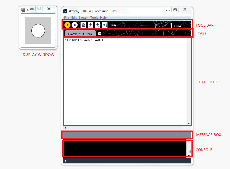
Launch the software and now what you see is the Processing Development Environment. And yes it looks like a color changed Arduino IDE. It consists of a text editor, a compiler, and a display window
Access Example Codes
Click on File menu

You’ll find “Examples”. Click on that and a new window will pop-up

Here you will find number of examples which teaches how to use each and every functions present in the software. And the best part is that it has been categorized very neatly so we can easily find what we want.
Running an Example code
We’ll basically we are interested in making our computer communicate with our development board so let us start with a program related to serial communication first.
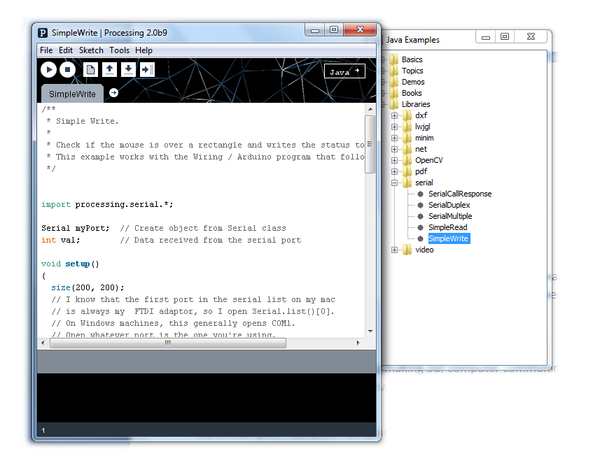
Go to Examples->Libraries->serial and double-click “SimpleWrite” to open the program

Now of course the program is 100% correct but it needs a small change to run according to our need. We need to change the COM Port number depending upon which COM port your device (Arduino/ ATmega8/ ATmega16 dev. board) is connected to.
For this, first find the following line in the program
String portName = Serial.list()[0];
Now replace “Serial.list()[0]” with the COM port number to which the development board is connected. In my case it was connected to COM9 so I edited it like this:
String portName = “COM9”;
What the processing Code does?
Well basically it starts a serial communication with the device connected at the COM port mentioned by us. Then it continuously sends the character “H” (if the mouse pointer is on the rectangle) or “L” (if the mouse pointer is moved away from the rectangle) to the device.
Now let us look into the code for our development board which would be used to test the processing code.
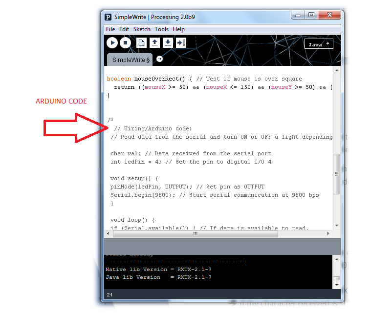
Note: The code for Arduino is given within the processing code as comments below the actual code. Scroll a bit down in the example program and you will find it there.
ATmega16 Code Explanation
-Initialize the USART function of the controller with required baud rate.
-Set PORTB’s first pin (i.e. PB0) as output.
-Enter into an infinite loop.
-Read a character from the RX line using the “BlueRdChar()” function.
-If the character received is “L” then turn OFF the LED at PB0 or if the character is “H” then turn ON the LED
Setup Instruction
1. Burn the given “Test.hex” file into the microcontroller or use the given c program to compile and generate the hex file on your own using a suitable complier like WINAVR with ATMEL STUDIO/AVR STUDIO or other software.
Since our board is supposed to run at 16MHz make sure the fuses of the IC are set as follows:
High fuse=0xC9
Low fuse=0xFF
(Warning: Be very careful while programming the fuse bits. If you set it with wrong values then the microcontroller may be permanently disabled.)
2. Connect the development board to the computer. Then RUN the code by clicking on the symbol.

3. Now hover the mouse pointer over the rectangle and if everything is done correctly then you should see the LED connected to the development board turn ON
This is just an example code and there is lot more you can do with this software which I would be showing you in the next tutorial.
Here is the video demo for it:
Processing is a Java based open source programming language and IDE (Integrated development environment) used for writing and running programs on a computer.
The main advantage of Processing is that it allows people with less or no knowledge on programming also to learn programming easily and become experts. Processing accomplishes this by providing numerous examples and tutorials pre-loaded in the software itself.
What we will use Processing is for letting our development board (Arduino/ ATmega8 Dev. Board/ ATmega16 dev. board) to communicate with the PC/ Laptop running Processing.
Software Requirements
1. PC/ Laptop running Windows 7/XP
2. Java Development Kit 7 (Download at www.oracle.com)
3. Processing 2.0 or above (Download at http://processing.org/download)
Hardware Required (For Testing)
1. Arduino/ ATmega16 / ATmega8 Development board running at 16MHz
2. 1 x LED
3. 1 x 330 ohms resistor
4. USB to UART adapter
Processing Development Environment (PDE)
Launch the software and now what you see is the Processing Development Environment. And yes it looks like a color changed Arduino IDE. It consists of a text editor, a compiler, and a display window
Access Example Codes
Click on File menu
You’ll find “Examples”. Click on that and a new window will pop-up
Here you will find number of examples which teaches how to use each and every functions present in the software. And the best part is that it has been categorized very neatly so we can easily find what we want.
Running an Example code
We’ll basically we are interested in making our computer communicate with our development board so let us start with a program related to serial communication first.
Go to Examples->Libraries->serial and double-click “SimpleWrite” to open the program
Now of course the program is 100% correct but it needs a small change to run according to our need. We need to change the COM Port number depending upon which COM port your device (Arduino/ ATmega8/ ATmega16 dev. board) is connected to.
For this, first find the following line in the program
String portName = Serial.list()[0];
Now replace “Serial.list()[0]” with the COM port number to which the development board is connected. In my case it was connected to COM9 so I edited it like this:
String portName = “COM9”;
What the processing Code does?
Well basically it starts a serial communication with the device connected at the COM port mentioned by us. Then it continuously sends the character “H” (if the mouse pointer is on the rectangle) or “L” (if the mouse pointer is moved away from the rectangle) to the device.
Now let us look into the code for our development board which would be used to test the processing code.
Note: The code for Arduino is given within the processing code as comments below the actual code. Scroll a bit down in the example program and you will find it there.
ATmega16 Code Explanation
-Initialize the USART function of the controller with required baud rate.
-Set PORTB’s first pin (i.e. PB0) as output.
-Enter into an infinite loop.
-Read a character from the RX line using the “BlueRdChar()” function.
-If the character received is “L” then turn OFF the LED at PB0 or if the character is “H” then turn ON the LED
Setup Instruction
1. Burn the given “Test.hex” file into the microcontroller or use the given c program to compile and generate the hex file on your own using a suitable complier like WINAVR with ATMEL STUDIO/AVR STUDIO or other software.
Since our board is supposed to run at 16MHz make sure the fuses of the IC are set as follows:
High fuse=0xC9
Low fuse=0xFF
(Warning: Be very careful while programming the fuse bits. If you set it with wrong values then the microcontroller may be permanently disabled.)
2. Connect the development board to the computer. Then RUN the code by clicking on the symbol.
3. Now hover the mouse pointer over the rectangle and if everything is done correctly then you should see the LED connected to the development board turn ON
This is just an example code and there is lot more you can do with this software which I would be showing you in the next tutorial.
Here is the video demo for it: