
Introduction
Normal DC motors just require power supply(+V and GND) and are controlled by switching it ON/OFF or by varying the amount of power supplied to it but in case of servo motors we generally need a microcontroller to control them since it needs a special signal along with the normal power supply(+V,GND and SIG). This circuit will show how to control a servo without using a microcontroller.

Description
The circuit uses a 555 Timer IC which is very cheap when compared to a microcontroller and also which doesn’t require programming. The 555 IC is configured in Astable Mode to generate the “Special Signal” for the servo motor to work. First let us understand that signal.
Here the special signal is nothing but a Pulse Width Modulated signal usually with a frequency of 50Hz (i.e. a Time Period of 20msec) or 25Hz (Time Period 40msec). The angle of the servo varies according to the ON time period of the signal (which is also known as the duration of the pulse or the width of the pulse.)
Different manufacturer define different pulse widths for their servo angles which would be mentioned in their datasheet. For example, the servo I am using (VTS-08B) sets the angle at -90o when the pulse width is 0.6msec, +90o when it is 2.4msec and 1.5msec for the neutral position (0o)
Timing Diagram:

Design Process:
So now we need to design the circuit in such a way that it can generate a signal of 50Hz frequency (i.e. a pulse generated once every 20ms) and whose pulse width can be varied from 0.6msec to 2.4msec. Note that here the duty cycle is less than 50% and hence normal Astable mode cannot be used.
The design equation is:
So for achieving 0.6msec on the lower side to 2.4msec on the higher side I should be able to vary the resistance of R at least from 27k to 109k. So I will use a variable resistor of value 100k and a fixed resistor of value 20k connected in series which will enable me to vary R from 20k (20k+0) to 120k (20k+100k).
By adjusting the knob of the potentiometer (variable resistor), we would be able to vary the angle of servo from -90o to +90o
Note 1: It is impossible (and not necessary) to choose a resistor with exact ranges. For example, take my case where I actually need a 27k fixed resistor and 82k variable resistor to get the exact range but it is not possible. So I chose a range (20k to 120k) which is wider then my required range.
Note 2: R3 can be of any value above 1 Mega Ohms.
POWER SUPPLY CIRCUIT:
Servo Motors need a minimum of 4.8V and can bear up to 6V of input voltage. We’ll stick to the standard 5V. For this we will use the good old 7805 IC. Now the problem with IC 7805 is that it can only provide a maximum current of 1A and some servos (especially large ones) take more than 1A while starting. So a Heat-sink is attached to the regulator IC to increase its maximum ratings.
The capacitors attached to the regulator will help in filtering out the unwanted spikes and also provide some initial boost for the Servo motor.
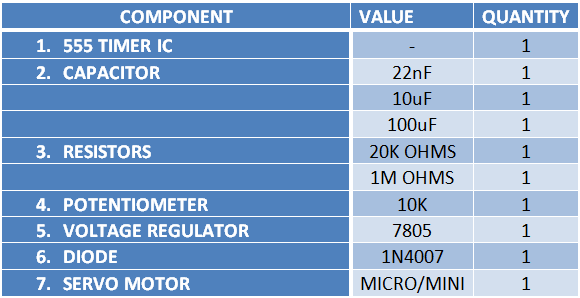
Now let’s list out the components required:
Advantages of this circuit:
1. Very cheap (under 1$)
2. Requires minimum components
3. Easy to design
4. Programming not required
Normal DC motors just require power supply(+V and GND) and are controlled by switching it ON/OFF or by varying the amount of power supplied to it but in case of servo motors we generally need a microcontroller to control them since it needs a special signal along with the normal power supply(+V,GND and SIG). This circuit will show how to control a servo without using a microcontroller.
Description
The circuit uses a 555 Timer IC which is very cheap when compared to a microcontroller and also which doesn’t require programming. The 555 IC is configured in Astable Mode to generate the “Special Signal” for the servo motor to work. First let us understand that signal.
Here the special signal is nothing but a Pulse Width Modulated signal usually with a frequency of 50Hz (i.e. a Time Period of 20msec) or 25Hz (Time Period 40msec). The angle of the servo varies according to the ON time period of the signal (which is also known as the duration of the pulse or the width of the pulse.)
Different manufacturer define different pulse widths for their servo angles which would be mentioned in their datasheet. For example, the servo I am using (VTS-08B) sets the angle at -90o when the pulse width is 0.6msec, +90o when it is 2.4msec and 1.5msec for the neutral position (0o)
Timing Diagram:
Design Process:
So now we need to design the circuit in such a way that it can generate a signal of 50Hz frequency (i.e. a pulse generated once every 20ms) and whose pulse width can be varied from 0.6msec to 2.4msec. Note that here the duty cycle is less than 50% and hence normal Astable mode cannot be used.
The design equation is:
Pulse Width T = R x C1
I take C1=22nF (since I have that already). Now the only variable here is R. So let us write the equation in terms of R.
R = T / C1
For -90o angle (T= 0.6ms), I get
R = (0.6x10⁻³) / (22x10-9)
=27kohms (approx.)
For +90o angle (T= 2.4ms), I get
R = (2.4x10⁻³) / (22x10-9)
=109kohms (approx.)
So for achieving 0.6msec on the lower side to 2.4msec on the higher side I should be able to vary the resistance of R at least from 27k to 109k. So I will use a variable resistor of value 100k and a fixed resistor of value 20k connected in series which will enable me to vary R from 20k (20k+0) to 120k (20k+100k).
By adjusting the knob of the potentiometer (variable resistor), we would be able to vary the angle of servo from -90o to +90o
Note 1: It is impossible (and not necessary) to choose a resistor with exact ranges. For example, take my case where I actually need a 27k fixed resistor and 82k variable resistor to get the exact range but it is not possible. So I chose a range (20k to 120k) which is wider then my required range.
Note 2: R3 can be of any value above 1 Mega Ohms.
POWER SUPPLY CIRCUIT:
Servo Motors need a minimum of 4.8V and can bear up to 6V of input voltage. We’ll stick to the standard 5V. For this we will use the good old 7805 IC. Now the problem with IC 7805 is that it can only provide a maximum current of 1A and some servos (especially large ones) take more than 1A while starting. So a Heat-sink is attached to the regulator IC to increase its maximum ratings.
The capacitors attached to the regulator will help in filtering out the unwanted spikes and also provide some initial boost for the Servo motor.
Now let’s list out the components required:
Advantages of this circuit:
1. Very cheap (under 1$)
2. Requires minimum components
3. Easy to design
4. Programming not required