
Introduction
Are you an electronic hobbyist? Then an adjustable power supply is a must for your various needs. This project explains how to make a LM317 based adjustable power supply unit with a digital display.
Components Required
1. LM317 IC
2. Resistor – 240 Ohms
3. Capacitors – 0.1uF, 10uF
4. Potentiometer – 5k
5. 30V/1A Adapter (or a transformer + Bridge wave rectifier IC)
6. ATMega16 Developments Board
7. 16 x 2 LCD Board
Circuit Design
Well the power supply circuit is very simple and can be found in the datasheet of LM317 itself.
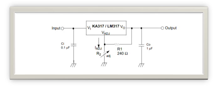
The output voltage is given by the equation,
But the problem is that ATmega16 can only take up to 5V. Input voltage more than that can fry up the controller.
Solution: A Voltage divider circuit!

Here R1 and R2 are the resistors and Vin is the input voltage. The output voltage Vout is given as:
So here maximum Vin = 30V and maximum Vout = 5V
Substituting in equation (1) and on solving, we get
R1:R2 = 5 : 1
So we can take R1= 5kΩ and R2=1kΩ
Code Explanation:
- Initialize the 16 bit ADC mode of the controller
- Initialize the LCD function
- Enter an infinite loop
- Read the voltage level at ADC1, convert it into a 16-bit discreet value (0 to 1023) and store it in a variable “val”.
- Divide the value at “val” by 1024 and then multiply it with 30. This gives you the original applied voltage value.
- Now display this value in the LCD
Conversion Process Example
-Let us say that we applied some input voltage Vin= 24V to the system
-Now from the design equation the output voltage of voltage divider circuit can be calculated. Here the output would be 4V which is the input to the ADC pin of microcontroller
-The controller would covert the analog value (0-5V) into a discreet value of range, 0-1023. In this case the value would be around 819.
-Next, this discreet value is again converted into the original input voltage range which is 0-30V through programming. Here the value obtained would be 23.99, which is almost equal to 24V!

How we display decimals:
Let us say we got a value val = 24.93
Now “lcd_write_int()” function only accepts whole numbers and no decimal part.
So what we do is,
Step 1: Multiply ‘val’ with 100
Val x 100 = 24.93 x 100 = 2493 (say we name it ‘a’)
Step 2: Obtain integer part by using ‘/ ’operator
I = a / 100 = 2493 / 100 = 24 (Integer)
Step 3: Obtain decimal part as another integer using ‘%’ operator
D = a % 100 = 2493 % 100 = 93
Step 4:First display the integer part followed by ‘.’ and then the decimal part.
Example: display(I+’.’+D) I.D

Are you an electronic hobbyist? Then an adjustable power supply is a must for your various needs. This project explains how to make a LM317 based adjustable power supply unit with a digital display.
Components Required
1. LM317 IC
2. Resistor – 240 Ohms
3. Capacitors – 0.1uF, 10uF
4. Potentiometer – 5k
5. 30V/1A Adapter (or a transformer + Bridge wave rectifier IC)
6. ATMega16 Developments Board
7. 16 x 2 LCD Board
Circuit Design
Well the power supply circuit is very simple and can be found in the datasheet of LM317 itself.
The output voltage is given by the equation,
Vout = 1.25 (1+ R2/R1) + Iadj x R2
What we need to design is the additional voltmeter kind of arrangements using a microcontroller in order to display the output voltage value accurately. For this, we use the ADC feature of the microcontroller.But the problem is that ATmega16 can only take up to 5V. Input voltage more than that can fry up the controller.
Solution: A Voltage divider circuit!
Here R1 and R2 are the resistors and Vin is the input voltage. The output voltage Vout is given as:
Vout = Vin X R2/(R1 + R2) . . . . . . . . . . . . . . . (1)
We choose the resistor values based on our requirements. Like say now our maximum voltage to be measured is 30V but we can only give up to 5V to our controller.So here maximum Vin = 30V and maximum Vout = 5V
Substituting in equation (1) and on solving, we get
R1:R2 = 5 : 1
So we can take R1= 5kΩ and R2=1kΩ
Code Explanation:
- Initialize the 16 bit ADC mode of the controller
- Initialize the LCD function
- Enter an infinite loop
- Read the voltage level at ADC1, convert it into a 16-bit discreet value (0 to 1023) and store it in a variable “val”.
- Divide the value at “val” by 1024 and then multiply it with 30. This gives you the original applied voltage value.
- Now display this value in the LCD
Conversion Process Example
-Let us say that we applied some input voltage Vin= 24V to the system
-Now from the design equation the output voltage of voltage divider circuit can be calculated. Here the output would be 4V which is the input to the ADC pin of microcontroller
-The controller would covert the analog value (0-5V) into a discreet value of range, 0-1023. In this case the value would be around 819.
-Next, this discreet value is again converted into the original input voltage range which is 0-30V through programming. Here the value obtained would be 23.99, which is almost equal to 24V!
How we display decimals:
Let us say we got a value val = 24.93
Now “lcd_write_int()” function only accepts whole numbers and no decimal part.
So what we do is,
Step 1: Multiply ‘val’ with 100
Val x 100 = 24.93 x 100 = 2493 (say we name it ‘a’)
Step 2: Obtain integer part by using ‘/ ’operator
I = a / 100 = 2493 / 100 = 24 (Integer)
Step 3: Obtain decimal part as another integer using ‘%’ operator
D = a % 100 = 2493 % 100 = 93
Step 4:First display the integer part followed by ‘.’ and then the decimal part.
Example: display(I+’.’+D) I.D
This article was published by me on EngineersGarage