
Introduction:
This article will show you how to make your own Serial Port Communication software interface (which is basically a Windows Form Application) using Microsoft Visual Studio 2012. This can be used for both wired (USB to UART/USB to Serial) and wireless (Bluetooth) serial communications.
We’ll test the software using an ATmega16 development Board or an equivalent circuit.
Software Required:
Microsoft Visual Studio 2010 or above (I used VS 2012 but 2010 would also work.)
System Requirements:
1. 1.6 GHz or faster Processor
2. 1 GB RAM (2 GB recommended)
3. 10 GB Hard Disk space
4. DirectX 9 capable video card running at 1024x768 or higher resolution
Make sure your PC/Laptop’s configuration matches the system requirements of the software. Right-click on the “My Computer” icon and go to “properties” to see your system configurations.
Components Required:
1. Atmega16 development board with 16MHz crystal
2. Serial Bluetooth Module(AUBTM/HC-05/HC-04/BLUSMIRF)
3. PC/Laptop running Windows 7/8
4. USB Bluetooth (Not required if you laptop/PC has inbuilt hardware)
Note: If you want a wired connection then no need of the Bluetooth devices. Instead you’ll need a USB to UART converter OR (USB to RS-232 + RS-232 to UART converter) along with necessary drivers installed in your computer.
Block-Diagrams:
WIRELESS (BLUETOOTH):

WIRED, USB TO UART:

WIRED, USB to RS-232 + RS-232 to UART:

Whichever type of connection you use, make sure that you are aware of the COM port number the particular device is attached to. Connect the device and go to System Properties> Device Manager and look out for the device by its name to see the COM port number.
Creating the Application:
Part 1: Designing The User Interface
1. Open Microsoft Visual Studio program. Go to FILE > New > Project

2. A window would pop up asking you which type of project and the project name. Select “Windows Form Application Visual C#”, and give a name to your project and then click “ok”.

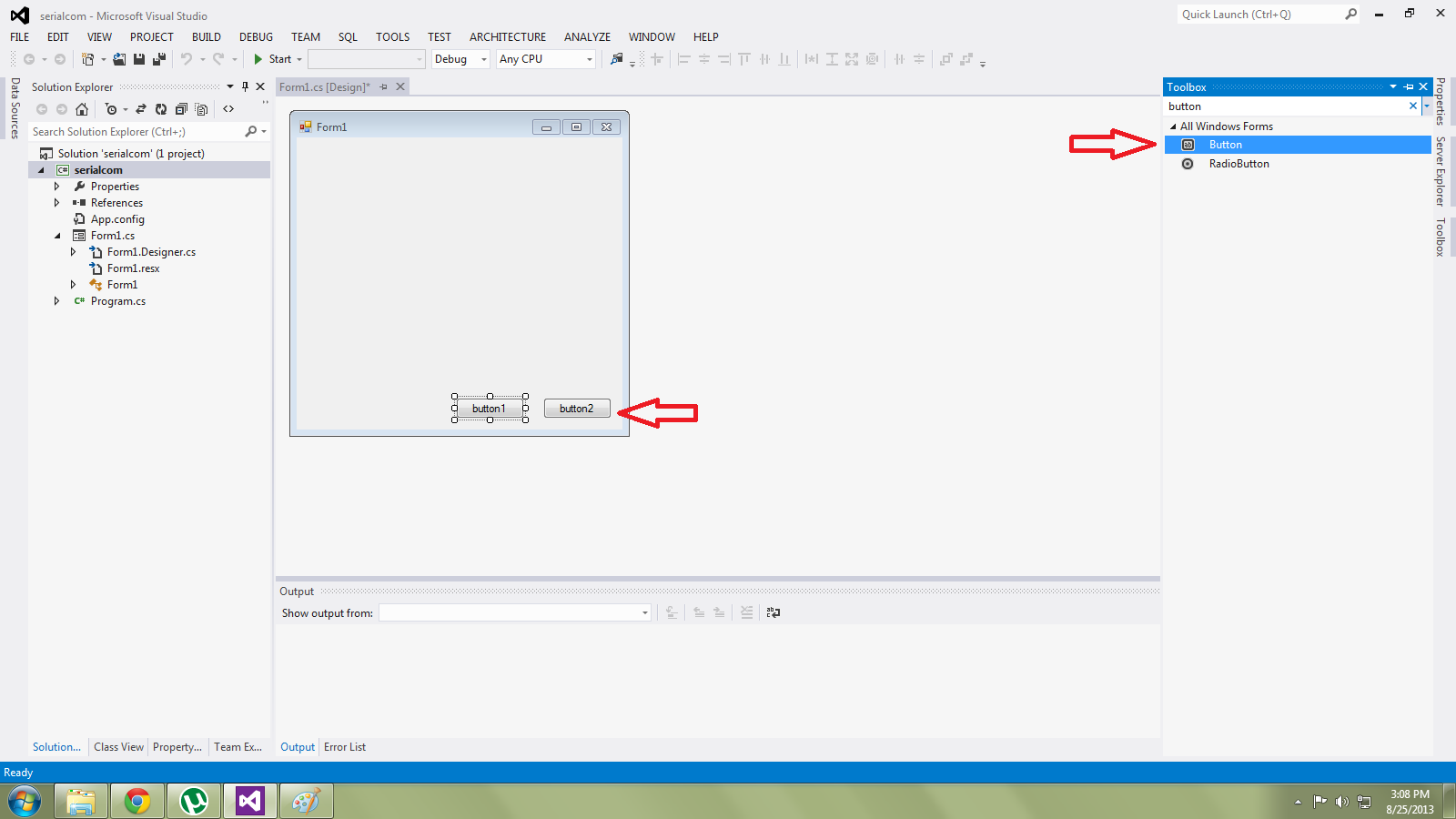
3. After few moments you will see the following screen. This is the Design tab where your app’s GUI is shown (Note that it is empty). Now click on the “Toolbox” present on the right side of the page.

4. Now you will see a huge list of components available in the Toolbox which can be used in our application. We don’t need all of them so we’ll use the search bar on top to pick the necessary components.

5. First, add the buttons. Search for it using the search bar. Click on “Button” and bring the mouse pointer inside the Form1 and click on it. You will see that “button1” appears inside the form now. Repeat the step and the next one would automatically be named as “button2”. We need three buttons in total (CONNECT, DISCONNECT, SEND).
6. Next add two “TextBox”. One will be used for viewing what we are transmitting and other box would show what is being received.

7. The receiver window needs to show multiple lines so click on the small arrow mark on the TextBox and check the “MultiLine” option. Now you can extend the box height wise also.

8. Now add two “labels”. Place one above transmitting window and another above receiving window.

9. Next, we need to rename every component neatly so that it is understandable and meaningful. Click on a specific button and then click on “Properties” located on the right side of the screen. A huge list of properties appear but edit only the “Text” and “(Name)” as follows:
Button1 –CONNECT
Button2 –DISCONNECT
Button3 –SEND
Label1 –TX WINDOW
Label2 –RX WINDOW


Now click on the “TextBox” and go to properties. You will notice that it consist of only “(Name)” and no “Text”. Rename the “(Name)” column as follows:
TextBox1 – TXWINDOW
TextBox2 – RXWINDOW
10. Now go to toolbox and double-click on “SerialPort”. “serialPort1” appears below the form.

We are done with the design part. Next we need to write the program to make the components we added functional and communicate with each other.
Part 2: Developing The Code
The code snippets would be followed by the explanation as to what it does.
1. Double-click on the CONNECT button. Now the program tab will open. You will notice that a part of the code has already been written automatically (This is saves time and also enables even beginners with less knowledge to create applications). The cursor will end up inside a function named “CONNECT_Click”. Copy-paste the following code inside that function
serialPort1.PortName = "COM2";
serialPort1.BaudRate = 9600; // Desired Baudrate
serialPort1.Open();
if (!serialPort1.IsOpen) return;
CONNECT.Enabled = false;
When CONNECT is clicked, it creates a serial connection with the given port number and desired baud rate and then disables the CONNECT button.
Note: My device is connected to COM port 2 so I wrote “COM2” here. You need to change the number depending on which port your device is connected to.
2. Come back to the design tab and now double-click “DISCONNECT” button. The cursor will go inside a function called “DISCONNECT_Click”. Type the following code inside it.
if (serialPort1.IsOpen)
serialPort1.Close();
CONNECT.Enabled = true;
This would close the serial port and re-enable the CONNECT button when DISCONNECT is clicked.
3. Next again go back to design tab and double-click “SEND” button. You will end up inside a function “SEND_Click”. Type the following:
String tx = TXWINDOW.Text;
serialPort1.Write(tx);
TXWINDOW.Clear();
Now when “SEND” is clicked (after typing something in TXWINDOW), the character inside TXWINDOW gets transferred into variable “tx” and then is transmitted through the serial port. Then the TXWINDOW is cleared.
4. Now add this code below the “SEND_Click” function.
private void Form1_FormClosing(object sender, FormClosingEventArgs e)
{
if (serialPort1.IsOpen) serialPort1.Close();
}
private void serialPort1_DataReceived(object sender, System.IO.Ports.SerialDataReceivedEventArgs e)
{
RxString = serialPort1.ReadExisting();
this.Invoke(new EventHandler(DisplayText));
}
private void DisplayText(object sender, EventArgs e)
{
RXWINDOW.AppendText(RxString);
}
->Form1_FormClosing function will be called when you click the “x” mark on the top-right corner your interface.
->serialPort1_DataReceived function tells the machine what to do with the received data. It saves the received data into the variable “RxString” and then calls DisplayText function.
->DisplayText function prints the sentence/word/character stored at “RxString” variable into the RX WINDOW.
We are done with the programming part also and the application should work perfectly. Now let us test it using an ATmega16 development Board.
Testing the Application:
1. Burn the given “Test.hex” file into the microcontroller or use the given c program to compile and generate the hex file on your own using a suitable complier like WINAVR with ATMEL STUDIO/AVR STUDIO or other software.
Since our board is supposed to run at 16MHz make sure the fuses of the IC are set as follows:
High fuse=0xC9
Low fuse=0xFF
(Warning: Be very careful while programming the fuse bits. If you set it with wrong values then the microcontroller may be permanently disabled.)
2. Turn ON the Bluetooth on your computer and also on the circuit setup.
3. Now open the Windows Form Application you have created. Click on DEBUG and then Start Debugging or directly Press F5 to start the application.

Your form application would pop-up like this.

Now click the “CONNECT” button and wait for few seconds to let the computer establish the connection.
4. Click inside the “TX” window, type some alphabet or number and press “send”. If everything is done correctly you should see something in “RX” window.

For example if I type ‘A’ in “TX” WINDOW and press send then in the “RX” window I get:
“Data Received: A”
Code Explanation:
Since our primary motive was to test our basic serial communication application, the code for the ATmega16 is made very simple and basic. We need to test two parameters of the application which is
1. Transmission of the data entered in TX WINDOW to the external device and
2. Reception and displaying the data in RX WINDOW coming from the external device (The development board)
Now let us see the algorithm of the code
-Initialize the USART of the microcontroller using BlueInit() function.
-Enter into an infinite loop.
-Read the data available at the RX pin of the controller using BlueRdChar() function and store it in character type variable named ‘value’.
-Write the string “Data Received:” into the UDR using BlueWrString() followed by the character stored in variable ‘value’ using BlueWrChar() and send it to the PC through the TX pin of the controller.
Troubleshooting:

A. If you get the above error then there are three possible mistakes
1. You didn’t turn ON the Bluetooth on your PC (in case of wireless connection) or didn’t connect the converter properly to the USB (in case of wired)
2. You have mentioned the wrong COM port number in the program.
3. You tried to send a character without clicking “CONNECT” first.

B. This type of error mostly occurs in wireless connections only. It’s probably because the Bluetooth devices are unable to communicate with each other. Restart the application and try again.
C. If the data you send and receive doesn’t match or if no data is being received.
-Make sure the baud rates mentioned in the programs are same.
-Check the power supply to the development board.
Conclusion:
You may ask “why to create my own interface when there are software(s) already available?” The answer is simple. Developing your own software enables customization which is not possible with commercial software(s). For example, take the project “Wireless PC Controlled Robot Using Bluetooth”. We had to enter specific alphabets and click “send” every time to control the robot. What if instead you had buttons neatly marked “FORWARD”, ”REVERSE”, etc. which when clicked changes the motion of the robot? .And also your name and your favourite logo on the interface panel. Something similar to this:

Cool isn’t it? This is possible only with own made interfaces.
This article was published by me on EngineersGarage