
Level:- Intermediate
You Require:-
1. RF Transmitter Receiver pair
2. HT12E, HT12D ENCODER DECODER
3. Resistors 33k, 750k
4. Switches X 4
5. Motor Driver IC L293D
Hardware
1. Chassis
2. 2X9V Geared DC Motors
3. Castor wheel
4. 2XWheels
5. 2X PCBs
This project would show you how to make a wireless robot using RF modules. Refer to Wireless Transmission to know the basics. Wireless toy cars works on same principle. This project would act as the basic platform for all other advanced robots. Here is the circuit of it.

This circuit uses RF module to control DC motors through a motor driver IC L293D. Transmission of signals is enabled by giving a low bit to pin14 (TE, active low) of encoder HT12E. The controls for motor are first sent to HT12E using the switches. Pins 10 and 11 are used to control one motor while pins 12 and 13 to control another motor. The data signals of encoder HT12E work on negative logic. Therefore a particular signal is sent by giving a low bit to the corresponding data pin of encoder.
The two motors can be controlled by input logic at pins 2 & 7 and pins 10 & 15. Input logic 00 or 11 will stop the corresponding motor. Logic 01 and 10 will rotate it in clockwise and anticlockwise directions, respectively. Thus, depending upon the signals generated at the transmission end, the two motors can be rotated in required directions.
After Testing the circuit on a Breadboard you can solder the components onto a PCB as I did. Be careful while soldering. Instead of directly soldering the ICs, solder the IC bases onto the PCB and then fix the ICs on them. By doing this, you can make sure that you don't damage the IC while soldering and also you can reuse the IC in your other projects.
 |
| Transmitter Board |
 |
| Switch Board |
I have soldered these switches in separate PCB so that I can use them in my other projects also. Using female burg wires I can connect this to the transmitter board.
 |
| Female Burg Wires Used For Connection |
The receiver circuit has been soldered onto a stripboard. Stripboard has number of connected lines which makes us easier to solder the circuit. A stripboard looks like this

The finished product looks like this
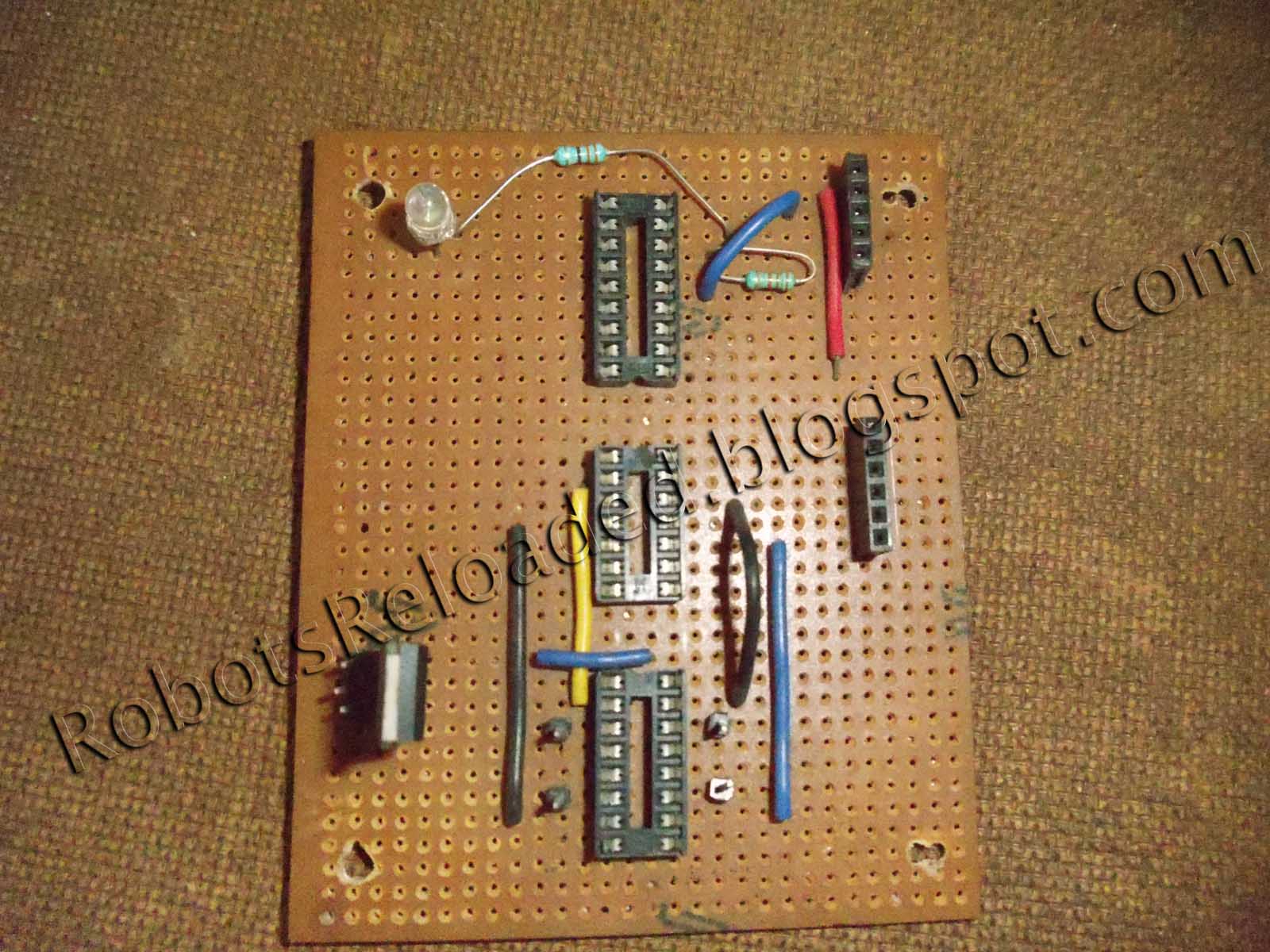 |
| Receiver Board |

Receiver Board
 |
| Wireless Robot |
That's all! You are done with making your first wireless robot !
Note that you can develop lot of projects basing on this. Let me give you one example. Just attach a wireless RF camera to the robot and the robot instantly turns into a spy robot ! Cool isn't it?
Here is the video of the robot in action
Here is the Breadboard Version of it