
Summary
Monitoring temperature of a particular place directly is difficult and sometimes impossible (ex: places where humans cannot be). So there is a necessity for wireless monitoring system which enables the user to track the temperature from a remote location.
In this article we’ll learn how to build a wireless temperature indicator which sends the temperature value to a PC/Laptop through Bluetooth.
Components Required
1. Atmega16 development board with 16MHz crystal
2. Serial Bluetooth Module(AUBTM/HC-05/HC-04/BLUSMIRF)
3. PC/Laptop running Windows XP/7/8
4. USB Bluetooth(Not required if you laptop/PC has inbuilt hardware)
5. LM35 Temperature Sensor
6. Breadboard
7. Solid Wires
Software Required
Your own software (Refer my previous tutorial) or any Serial Port Software on your PC (RealTerm/HyperTerminal/TeraTerm/Putty)
Block-Diagram
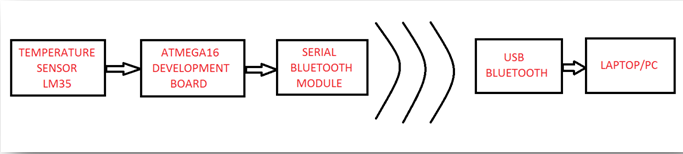
Process Explanation:
-The Temperature sensor LM35 produces an output voltage which is directly proportional to its surrounding temperature. For every 1°C of rise/fall in temperature, the output voltage of the sensor varies by 10mV.

-The output of this sensor is analog in nature which needs to be converted into a digital value using an Analog to Digital Converter (ADC) so it is fed into 37th pin (PA3) of PORT A of the ATmega16 microcontroller. ATmega16 consists of 8 channels ADC (PA0-PA7) with a maximum resolution of 10 bits. So the analog input is converted into a discreet value within a range of 0 to 1023 (210 discreet values)

-This discreet value needs to be converted into the Celsius scale value which is done by adding a conversion formula in the program:
((X/1023.00)*500.00)
Where “X” is an output value from the ADC and its range is 0 to 1023.
EXAMPLE:

-Next, the obtained temperature value is transmitted to the PC by using the USART feature of the microcontroller.
-The PC receives this data through Bluetooth and displays it on screen.
Code Explanation:
Basically, the code involves two parts:
1. ADC implementation
2. USART implementation
FUNCTIONS USED:
1. BlueInit()
It is used for initializing the USART function and setting the baud rate.
2. BlueRdChar()
Wait till a data is received at the RX pin. Once the data arrives it returns the data to the called function.
3. BlueWrChar(unsigned char d)
Writes the character stored in variable “d” into USART line which in turn transmits it to TX pin of controller.
4. BlueWrString(const char *msg)
This function is used when a group of characters (string) have to be transmitted.
5. BlueWrInt(int val,unsigned int field_length)
This function is used to transmit an integer value stored at “val” through the USART. The “field_length” is used to specify the number of digits.
6. SetADC()
This is used to enable the ADC feature of the controller.
7. ReadADC(uint8_t ch)
This function is used to read the analog voltage value at the particular ADC channel specified by the value at “ch” and then convert it into a discreet value of range 0 to 1023.
ALGORITHM:
Step 1: Initialize the ADC function and USART function with 9600 baud rate.
Step 2: Enter into an infinite loop
Step 3: Wait for a character to be available at RX pin of the controller using the BlueRdChar() function. If character is available, go to step 4 else wait.
Step 4: Store the available character in the variable named “value”.
Step 5: If the character stored in “value” is “s” or “S” then go to Step 6 else go to Step 3.
Step 6: Enter into the second infinite loop.
Step 7: Obtain the analog value at 3rd channel of ADC and convert it into discreet value between 0 and 1023 using ReadADC(3) function.
Step 8: Convert the discreet value into Celsius scale value using the conversion formula and store it a variable name “temp”.
Step 9: Send the string "The Current Temperature is:" using BlueWrString() function followed by the temperature value present at “temp” using BlueWrInt().
Step 10: Wait for 2 seconds and go back to Step 7.
Circuit Setup:

Setup Instructions:
1. Burn the hex file generated through the given C program. Remember that we need to run the controller using a external 16MHz crystal so change the fuse settings as follows:
High fuse=0xC9
Low fuse=0xFF
(Warning: Be very careful while programming the fuse bits. If you set it with wrong values then the microcontroller may be permanently disabled.)
2. Turn ON the Bluetooth on your computer and the circuit setup. Wait a moment to allow them to connect (Refer the previous tutorial if you are establishing a connection for the first time.)
3. Open the serial communication software on your PC and configure it as follows:
Baud: 9600
Port: <The port where the Serial Bluetooth Modem is virtually connected to>
Data bits: 8
Parity: None
Stop bits: 1
Hardware Flow Control: None
4. Enter the character ‘S’ or ‘s’ and press send. After a moment you should see the computer screen being updated with the temperature value in Celsius scale. Something like this:

VIDEO:
This article was published by me on EngineersGarage