Level : Beginners
You Require:
1. Power Supply Circuit (Click here if you've not seen it yet)
2. IC LM324 Op-Amp
3. IC L293D Motor Driver
4. Resistors 2X10kΩ, 2X330Ω
5. 2X IR LED Tx Rx pairs
6. 2X 10k Potentiometer
Hardware
1. Chassis
2. 2X9V Geared DC Motors
3. Castor wheel
4. 2XWheels
6. 2X 10k Potentiometer
Hardware
1. Chassis
2. 2X9V Geared DC Motors
3. Castor wheel
4. 2XWheels
Before going into the actual tutorial, let me explain you a small concept about light. You must be knowing that the light that strikes any platform is reflected. The reflection and absorption coefficient of light depend upon material, color of platform and other factors. In simple words the black surface absorbs the light and the white surface reflects it, this is the basic concept behind making a line follower.
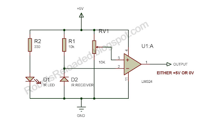
So our robot's sensor has two parts which are emitter and receiver. The emitter continuously emits the infrared light and the receiver absorbs it after getting reflected from the black or white surface. The voltage across the receiver is directly proportional to the reflected light it absorbs. So for white surface, maximum reflection occurs so maximum voltage across the receiver and vice-versa.
 |
| click on image to enlarge |
LM324 is used as a comparator here. We give a reference voltage to its input using a 10k pot. When the voltage across the receiver is less than this reference voltage, the comparator gives low output and when the voltage is more than the reference point, the comparator gives a high output.
The table below shows how the robot senses its position on the line:-
Motor Driver L293D
Well a LM324 IC cannot drive motors directly since it can't supply the power which can drive the motors. So we use a motor driver IC which takes a low voltage input and supplies high power to the motors
The table below shows the various input combinations and the direction of motion related to that combination:-
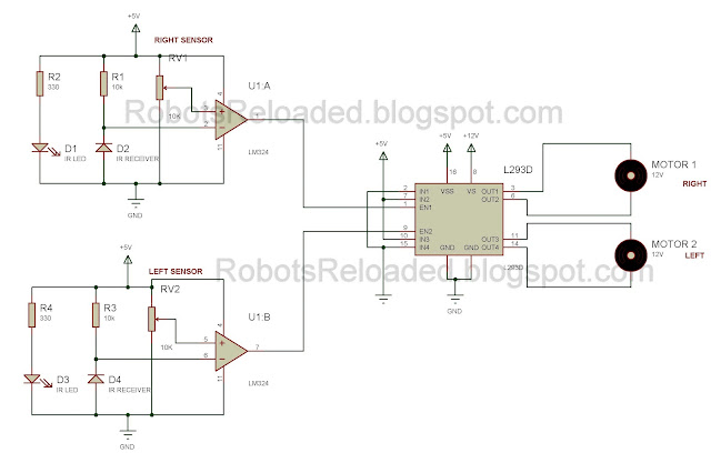
There are two enable pins for this IC, one is for Motor 1 and other is for Motor 2. The Motor would be only enabled if this pin is provided with logic high, or else the motor would stop. We connect the sensor output to the two enable pins. I guess you must have already got the idea as to how to connect the comparator's output to the motor driver's Enable pins. Still didn't get it? then look at the image below.
The Input pins 2 and 15 are grounded and pins 7 and 10 are supplied with 5 volts so when the motors are enabled, they will only in forward direction.
Attach the motors and castor wheel to the chassis and fit in the wheels into the motor shaft. Connect the wires coming from motor to the output of the motor driver IC. Thats all! Your own made Autonomous Line Follower Robot is ready to run now!
 |
| click on image to enlarge |
The table below shows how the robot senses its position on the line:-
| click on image to enlarge |
Motor Driver L293D
Well a LM324 IC cannot drive motors directly since it can't supply the power which can drive the motors. So we use a motor driver IC which takes a low voltage input and supplies high power to the motors
 |
| click on image to enlarge |
There are two enable pins for this IC, one is for Motor 1 and other is for Motor 2. The Motor would be only enabled if this pin is provided with logic high, or else the motor would stop. We connect the sensor output to the two enable pins. I guess you must have already got the idea as to how to connect the comparator's output to the motor driver's Enable pins. Still didn't get it? then look at the image below.
 |
| click on image to enlarge |
Attach the motors and castor wheel to the chassis and fit in the wheels into the motor shaft. Connect the wires coming from motor to the output of the motor driver IC. Thats all! Your own made Autonomous Line Follower Robot is ready to run now!


what is ir reciever diode ?
ReplyDeleteIt is a photo diode with an IR filter (Looks black usually)
DeleteIf that's not available, you can use a plain photo diode.
what is the difference between VSS and VS
ReplyDeleteVS is the source voltage for the motors and VSS is the source voltage for the IC itself.
DeleteCan i USE 12V for both VSS and VS ?
ReplyDeleteNo, you should not. VSS cannot be more than 5V.
DeleteDo you used two LM324 for the circuit or only one.
ReplyDeleteOne LM324 IC has 4 op-amps so one enough.
Delete